Optical Fiber Cable Suited for Blown Installation or Pushing Installation in Microducts of Small Diameter
- Summary
- Abstract
- Description
- Claims
- Application Information
AI Technical Summary
Benefits of technology
Problems solved by technology
Method used
Image
Examples
Embodiment Construction
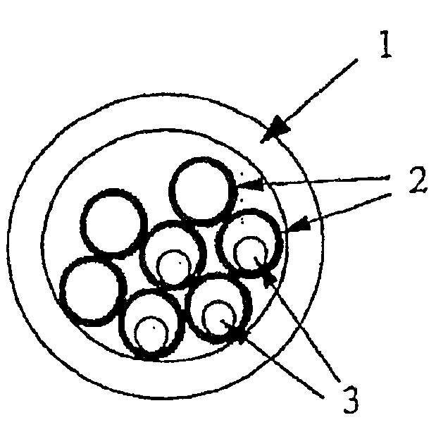
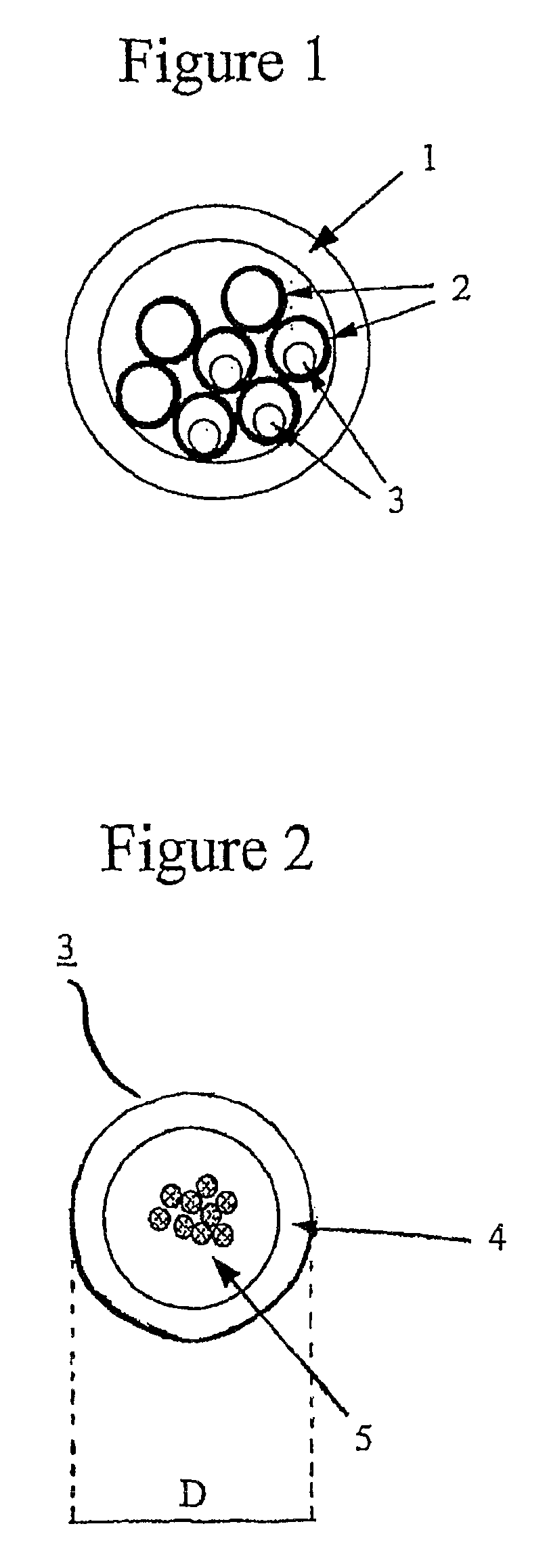
[0022] An exemplary embodiment of the present invention is explained with reference to FIGS. 1 and 2.
[0023]FIG. 1 shows an example of microcabling technology for the deployment of optical fiber cables. This configuration depicts a duct 1 in which seven microducts 2 have been placed. As depicted, four of the seven microducts 2 have a microcable 3 inside.
[0024]FIG. 2 shows a microcable 3 according to the present invention. It includes a single buffer tube 4 holding a plurality of optical fibers 5. The fibers do not have a fixed position within buffer tube 4, nor to each other. The buffer tube 4 functions as an outer sheath, which is typically smooth and free of recesses. A water-repelling gel (e.g., a thixotropic material) typically surrounds the optical fibers 5 within the buffer tube 4.
[0025] The buffer tube 4 of the microcable 3 is typically a homogeneous structure made of single polymeric material, more typically a thermoplastic material such as polyamide (i.e., nylon), polycar...
PUM
 Abstract
Description
Claims
Application Information
 - R&D
- Intellectual Property
- Life Sciences
- Materials
- Tech Scout
- Unparalleled Data Quality
- Higher Quality Content
- 60% Fewer Hallucinations
Browse by: Latest US Patents, China's latest patents, Technical Efficacy Thesaurus, Application Domain, Technology Topic, Popular Technical Reports.
© 2025 PatSnap. All rights reserved.Legal|Privacy policy|Modern Slavery Act Transparency Statement|Sitemap|About US| Contact US: help@patsnap.com


