
Mobile communication system for performing hand-off based on communication resources in base stations

Inactive Publication Date: 2007-08-09
FUJITSU LTD
View PDF30 Cites 15 Cited by
  • Summary
  • Abstract
  • Description
  • Claims
  • Application Information

AI Technical Summary

Benefits of technology

[0014] In this system, when a certain mobile station originates a call, the data rate of another mobile station is reduced if necessary. In this way, communication resources to be allocated to the mobile station which originates the call can be secured. The data rate of another mobile station can not only be adjusted using a call originating from a certain mobile station as a trigger, but it can also be increased when the call of a certain mobile station is released. Alternatively, when there is delay in communications of a certain mobile station, the data rate of the mobile station can be improved.
[0016] In this system, the usage of the communication resources of the radio transmission path to be managed by the based station is periodically informed to the base station control device. Therefore, the base station control device can allocate transmission line resources corresponding to the radio resources that the base station can allocate to the mobile station to the mobile station. In this way, radio resources and transmission line resources are never maintained unbalanced and the ineffective use of communication resources can be avoided.

Problems solved by technology

Therefore, if a hand-off method presuming voice communications is adopted in a mobile communication system mainly used for data communication, there is a possibility that a variety of inconveniences may occur.
In addition, if a communication resource management method presuming voice communications is adopted in a mobile communication system mainly used for data communication, there is a possibility that communication resources will not be efficiently used.
However, neither a detailed hand-off method for data communications (packet data communications and the like) nor a detailed communication resource management method for data communications have been proposed.
In particular, such methods have not been proposed in a mobile communication system adopting CDMA.

Method used


Image

  • Mobile communication system for performing hand-off based on communication resources in base stations
  • Mobile communication system for performing hand-off based on communication resources in base stations
  • Mobile communication system for performing hand-off based on communication resources in base stations

Examples


first embodiment

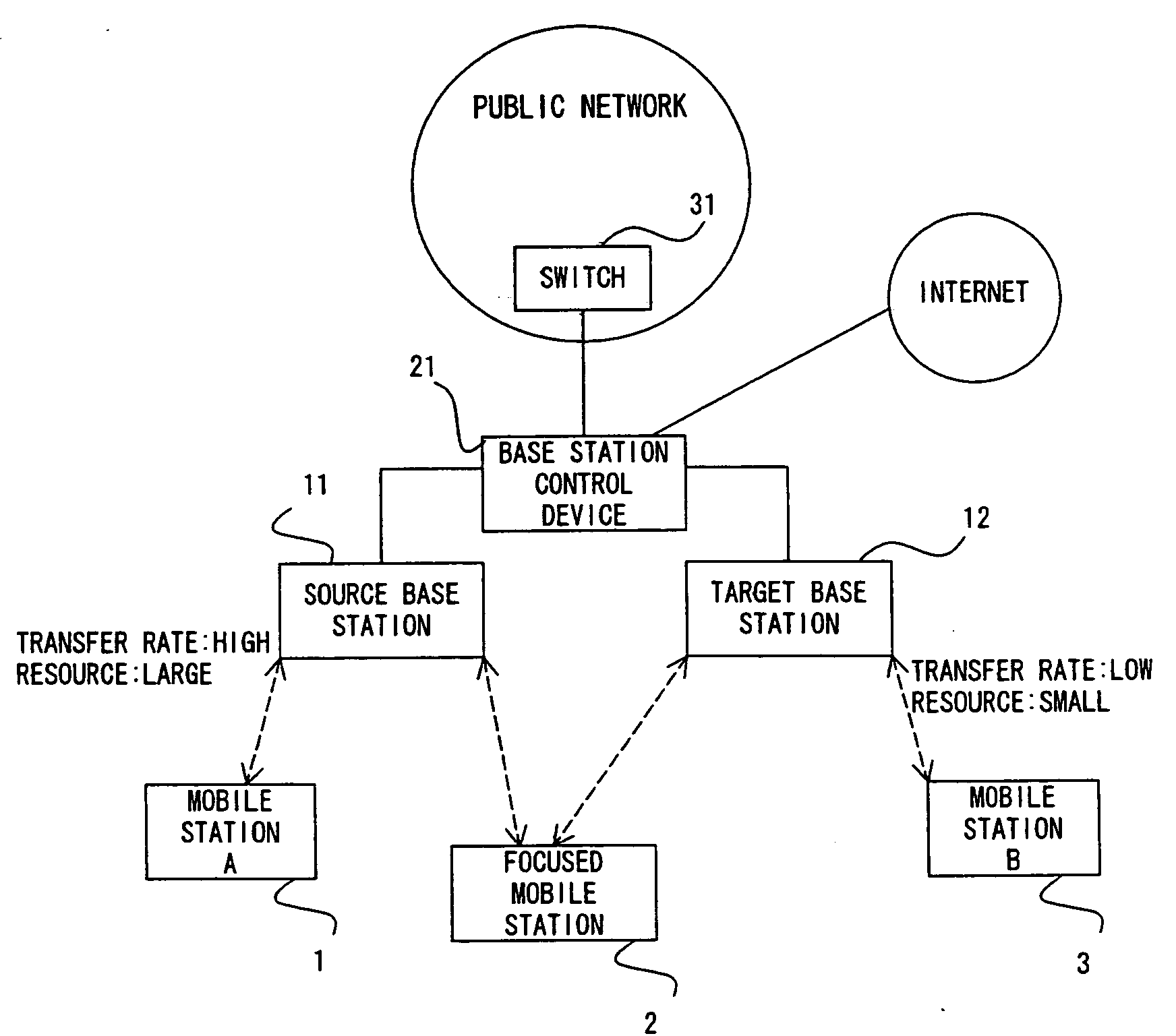
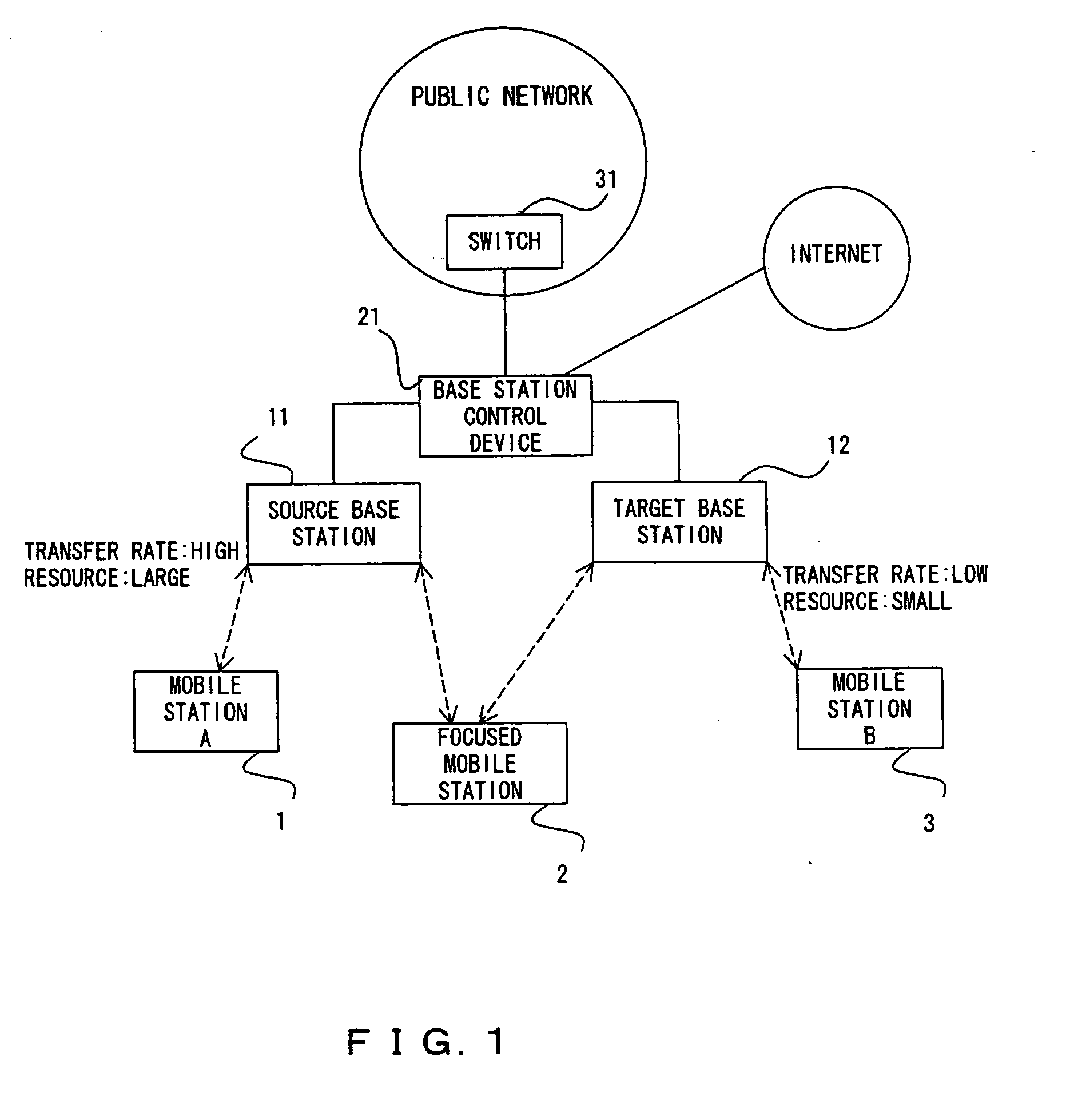
[0038]FIG. 1 shows the configuration of the mobile communication system of the preferred embodiment. Note that FIG. 1 shows only devices directly related to the present invention.

[0039] Mobile stations 1 through 3 are portable terminal devices, such as a telephone set, a PDA, a personal computer and the like. Each of the mobile stations 1 through 3 comprises an interface establishing a radio transmission path with one or more base stations and transmits / receives signals to / from the base station through the radio transmission path.

[0040] Base stations 11 and 12 each comprise an interface establishing a radio transmission path with each of the mobile stations 1 through 3 and accommodates the mobile stations 1 through 3. Each of the base stations 11 and 12 is connected to a base station control device 21 through a transmission line, and their operation is controlled by the base station control device 21. Here, although the transmission line is basically an optical fiber cable, a meta...

second embodiment

[0095] As described about the first embodiment, the maximum total transmitting power of a base station is predetermined and the data rate of a signal transmitted through a radio transmission path is also restricted accordingly. Therefore, for example, if high-speed packet data communications are attempted, the amount of communication resources that can be allocated to other communications become small, which affects other communications. In packet data communications, the data rate changes greatly. Therefore, if a large amount of communication resources is fixedly allocated to packet data communications, there are communication resources reserved without being used when the data rate of the packet data communications drops.

[0096] This problem can be solved if the amount of communication resources to be allocated to each connection and / or the data rate of each connection is dynamically adjusted, as requested.

[0097] In the mobile communication system according to the second embodime...

third embodiment

[0138] As shown in FIG. 21, a mobile station 41 is connected to a network through a base station 51 and a base station control device 61. A radio transmission path connects the mobile station 41 and base station 51, and a transmission line (an optical fiber, a metal cable or a radio transmission path) connects the base station device 51 and base station control device 61. In this system, the communication resources of the radio transmission path and those of the transmission line are managed by the base station 51 and base station control device 61, respectively.

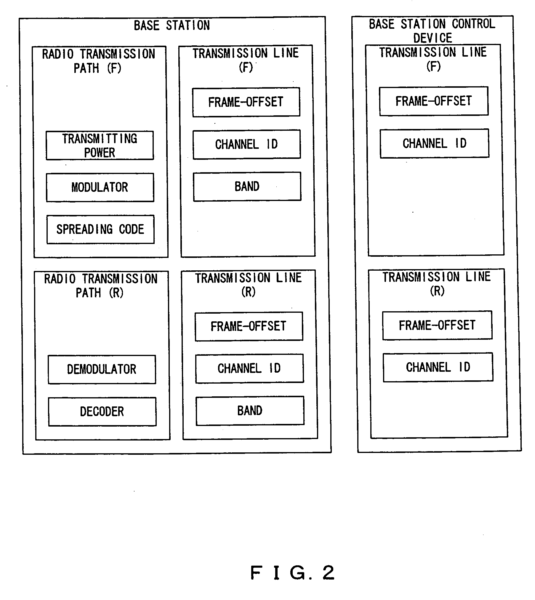
[0139] Although transmitting power, a modulator, a spreading code, a demodulator, a decoder and the like are managed as the communication resources of the radio transmission path, in the following description, attention is focused on the “transmitting power”. The transmitting power of each connection is proportional to the data rate of the connection. On the other hand, although a band, a frame-offset, a channel ID and the ...


PUM


Abstract

Each mobile station is accommodated in a base station through a radio transmission path. A base station control device controls each base station. A mobile station is accommodated in a first base station. Each of the base stations notifies the mobile station of the condition of the communication resources of the base station, respectively. If the mobile station judges that it is advantageous to be accommodated in a second base station instead of the first base station, the mobile station makes a request for hand-off to the base station control device. The base station control device issues a hand-off command to both of the first and second base stations. Then, the mobile station is accommodated in the second base station.

Description

CROSS REFERENCE TO RELATED APPLICATION [0001] This application is a continuation application of an International Application of PCT / JP00 / 06448, which was filed on Sep. 20, 2000. BACKGROUND OF THE INVENTION [0002] 1. Field of the Invention [0003] The present invention relates to a mobile communication system and in particular, relates to a mobile communication system adopting CDMA. [0004] 2. Description of the Related Art [0005] Recently, mobile communications have widely spread. In a mobile communication system, each mobile station is accommodated in the nearest base station and is connected to a network through the base station. In this case, since each base station accommodates as many subscribers as possible, usually radio signals are multiplexed when transmitted. For the multiplex method of radio signals, conventionally, Frequency-Division Multiple Access (FDMA) or Time-Division Multiple Access (TDMA) is adopted. However, in the next generation system, Code-Division Multiple Acc...

Claims


Application Information

Patent Timeline
IPC IPC(8): H04Q7/20H04W36/08H04W36/30H04W36/36H04W36/38H04W48/20
CPCH04W28/22H04W36/08H04W48/20H04W36/36H04W36/22H04W36/362
Inventor IGARASHI, HIRONOBUINOKO, KATSUTOSHIKURODA, YUJI
Owner FUJITSU LTD
Learn More