
Mixing-enhancement inserts for pulse detonation chambers

a technology of mixing enhancement and pulse detonation chamber, which is applied in the direction of intermittent jet plants, vessel construction, marine propulsion, etc., can solve the problems of inability to direct detonation initiation at the thrust wall, inconvenient engine design, and complicated pde of onboard oxidizers, so as to reduce the number of moving parts, reduce or eliminate the inefficient use of bleed air, and simple mechanical design

Inactive Publication Date: 2009-04-21
LOCKHEED MARTIN CORP
View PDF7 Cites 7 Cited by
  • Summary
  • Abstract
  • Description
  • Claims
  • Application Information

AI Technical Summary

Benefits of technology

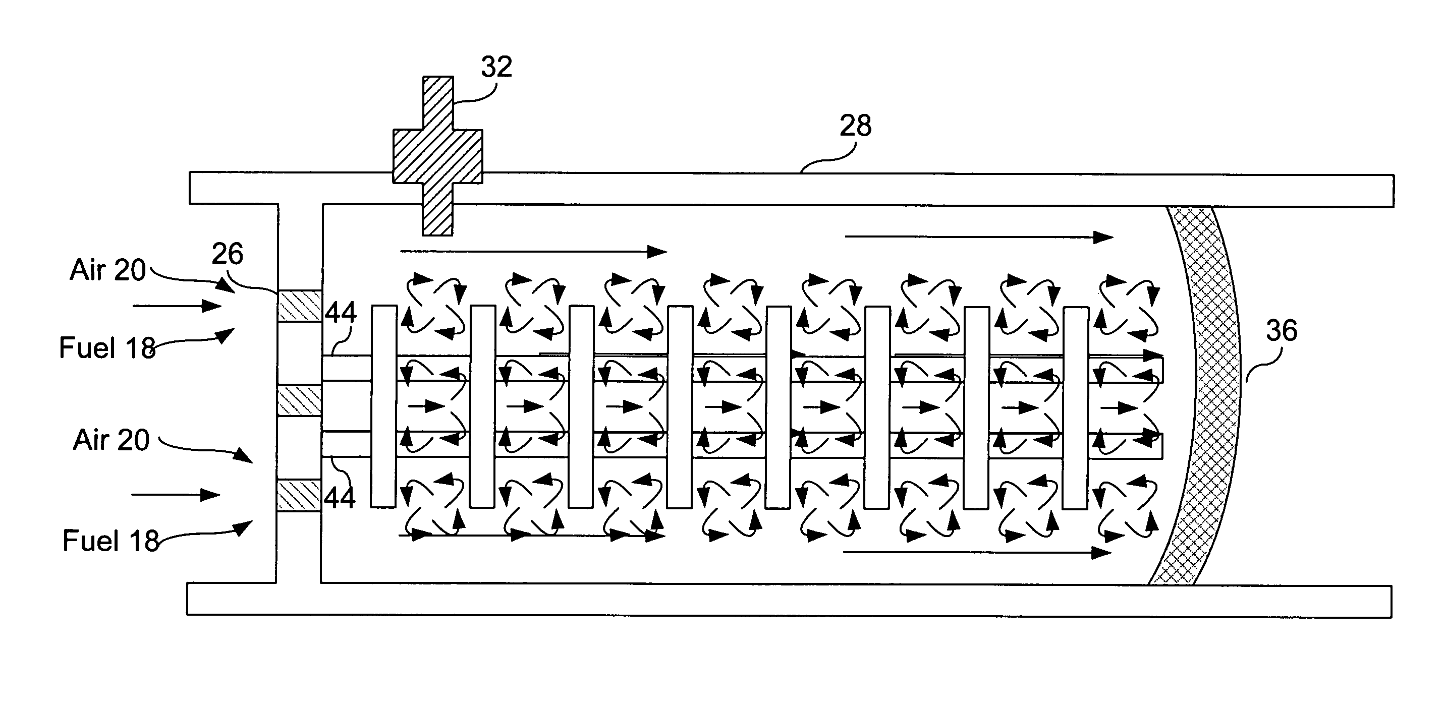
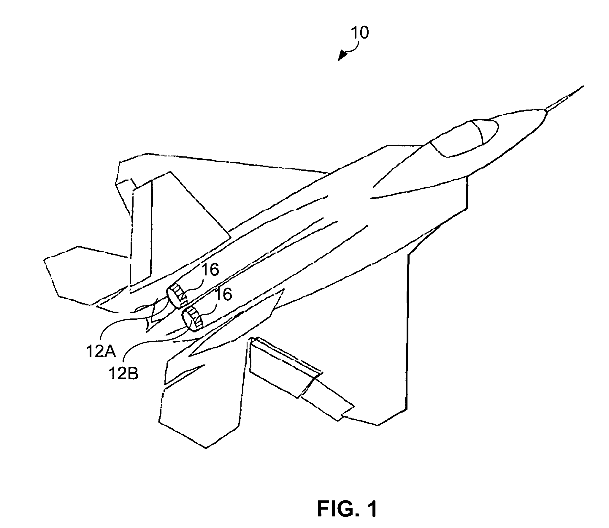
The present invention provides a pulse detonation chamber insert that can improve the performance of pulse detonation engines or actuators. The insert induces flow obstructions that enhance the mixing of oxidizer and fuel, reducing the detonation run-up distance and increasing thrust. The insert is made from materials resistant to the high pressure and temperature environment of the pulse detonation chamber. The invention also provides a pulse detonation engine that includes a distribution manifold, pulse detonation chamber, and igniter, and a hybrid pulse detonation engine that combines a conventional engine with a pulse detonation engine. The invention also provides a pulse detonation actuator that can manipulate fluid flow. The pulse detonation technology reduces the number of moving parts and inefficient use of bleed air, providing higher thermodynamic efficiency than conventional engines.

Problems solved by technology

For a PDE operating with a typical gas mixture of JP-10 fuel and air, direct detonation initiation at the thrust wall is not possible since the critical initiation energy is much too high for a practical ignition system.
The low reactivity of prototypic fuel air mixtures causes the detonation run-up distance to be relatively large and thus prohibitive for practical engine designs.
Although this may meet the objective of detonation initiation within a short distance, the need for an onboard oxidizer complicates the PDE by adding additional parts with associated cost and weight, while also imposing significant safety hazards.
The weight and cost of tactical aircraft exhaust systems have increased at an alarming rate with the incorporation of features for afterburning, thrust vectoring, and advanced shaping.
Aperture shaping for afterbody integration further imposes the use of less structurally efficient two-dimensional, rather than axis-symmetric, nozzles.
These capabilities require greater mechanical complexity in the various systems.
This solution, while effective, is not fuel efficient as significant amounts of unburned fuel are exhausted.
These actuators may add some complexity in exchange for reducing the weight of jet engines and their associated nozzle configurations.
However, bleeding air from the engine takes away mass flow rate of the primary flow, which reduces the thrust and efficiency of the jet engine.

Method used


Image

  • Mixing-enhancement inserts for pulse detonation chambers
  • Mixing-enhancement inserts for pulse detonation chambers
  • Mixing-enhancement inserts for pulse detonation chambers

Examples


Embodiment Construction

[0030]Preferred embodiments of the present invention are illustrated in the FIGUREs, like numerals being used to refer to like and corresponding parts of the various drawings.

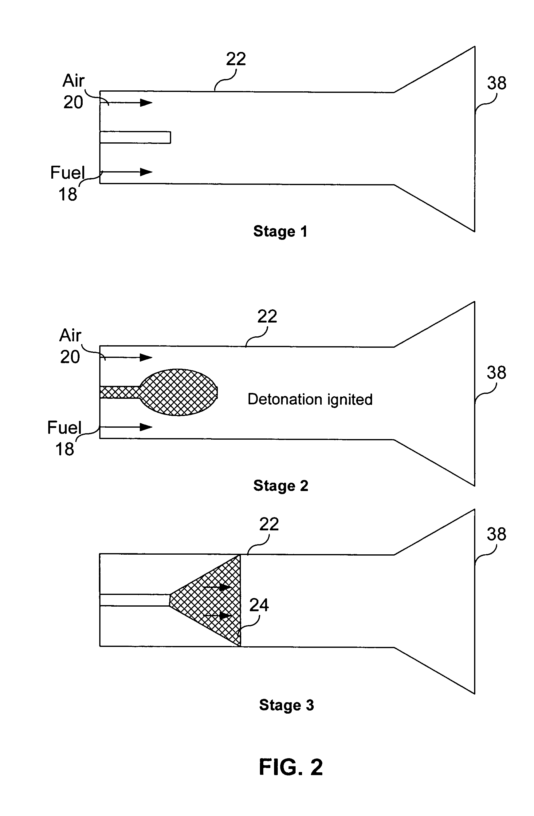
[0031]Pulse detonation is a propulsion technology that detonates fuel to produce thrust more efficiently than existing solutions. Pulse detonation engines produce a higher specific thrust and may be used as a part of a multi-stage propulsion system. Additionally, the pulse detonation engine may provide static thrust for ram-jet or scram-jet engines or operate in combination with turbo-fan systems. As such, many potential applications exist for pulse detonation engines.

[0032]Pulse detonation engines are an extension of pulse-jet engines that share many similarities. However, an important difference exists. Pulse detonation engines detonate rather than deflagrate their fuel. The detonation of fuel results in immense pressure which in turn may be used as thrust. Deflagration is a relatively gentle process of burni...


PUM


Abstract

The present invention provides a pulse detonation insert that induces flow obstructions within the pulse detonation chambers, wherein the flow obstructions are operable to induce turbulence within a primary fluid flow passing over the obstructions. This turbulence may take the form of vortices that enhance the mixing of the oxidizer and fuel within the primary flow. Additionally, supports couple to the pulse detonation chamber walls and flow obstructions to hold the flow obstructions in place within the pulse detonation chamber. The combustion / Detonation of the mixed oxidizing fuel results in an increased velocity of the primary flow exiting the pulse detonation chamber and reduced the amount of unburnt fuel within the exhaust.

Description

CROSS-REFERENCE TO RELATED APPLICATION[0001]This application is related to: U.S. Pat. No. 6,112,512 (the '512 patent) issued to Miller et al., filed Aug. 5, 1997 entitled “METHOD AND APPARATUS OF PULSED INJECTION FOR IMPROVED NOZZLE FLOW CONTROL”; U.S. Pat. No. 6,869,049 issued to Seyed Saddoughi, filed Jul. 24, 2002 entitled “METHOD AND APPARATUS FOR MODULATING FLOW SEPARATION”; U.S. Pat. No. 6,629,647 issued to Friedrich Boecking, filed Jun. 29, 2001 entitled “PRESSURE-CONTROLLED INJECTOR WITH CONTROLLED NOZZLE NEEDLE”; U.S. Pat. No. 5,473,885 issued to Hunter, Jr. et al., filed Jun. 24, 1994 entitled “PULSE DETONATION ENGINE,” which are all hereby incorporated by reference in their entirety.TECHNICAL FIELD OF THE INVENTION[0002]The present invention relates generally to the field of fluid flow control, and more particularly, to a system and method to enhance fuel and oxidizer mixing with increased turbulence provided by inserts located within pulse detonation chamber(s).BACKGROUN...

Claims


Application Information

Patent Timeline
Patent Type & Authority Patents(United States)
IPC IPC(8): F02K7/00F02C5/02
CPCB64C23/06F02C5/00F02K1/28F02K1/30F02K7/02F02K7/06Y02T50/162Y02T50/166B64C2230/18Y02T50/10
Inventor SADDOUGHI, SEYEDPINARD, PIERREBOESPFLUG, MATTHEWSTEENBURGH, DENNIS
Owner LOCKHEED MARTIN CORP
Learn More