Method of forming piezoelectric actuator of inkjet head

a piezoelectric actuator and inkjet head technology, applied in the field of inkjet head, can solve problems such as difficulty in forming the conventional piezoelectric layer

Inactive Publication Date: 2007-08-16
SAMSUNG ELECTRO MECHANICS CO LTD
View PDF6 Cites 22 Cited by
  • Summary
  • Abstract
  • Description
  • Claims
  • Application Information

AI Technical Summary

Benefits of technology

[0012]The present general inventive concept provides a method of forming a piezoelectric actuator of an inkjet head that can uniformly control a formation of an upper electrode and can prevent a short-circuit between the upper electrode and a lower electrode.

Problems solved by technology

However, since the conventional piezoelectric layer 42 formed by the screen-printing tends to spread laterally because of a property of the material of the paste state, it is difficult to form the conventional piezoelectric layer 42 in a uniform thickness.

Method used


Image

  • Method of forming piezoelectric actuator of inkjet head
  • Method of forming piezoelectric actuator of inkjet head
  • Method of forming piezoelectric actuator of inkjet head

Examples


Embodiment Construction

[0030]Reference will now be made in detail to the embodiments of the present general inventive concept, examples of which are illustrated in the accompanying drawings, wherein like reference numerals refer to the like elements throughout. The embodiments are described below in order to explain the present general inventive concept by referring to the figures.

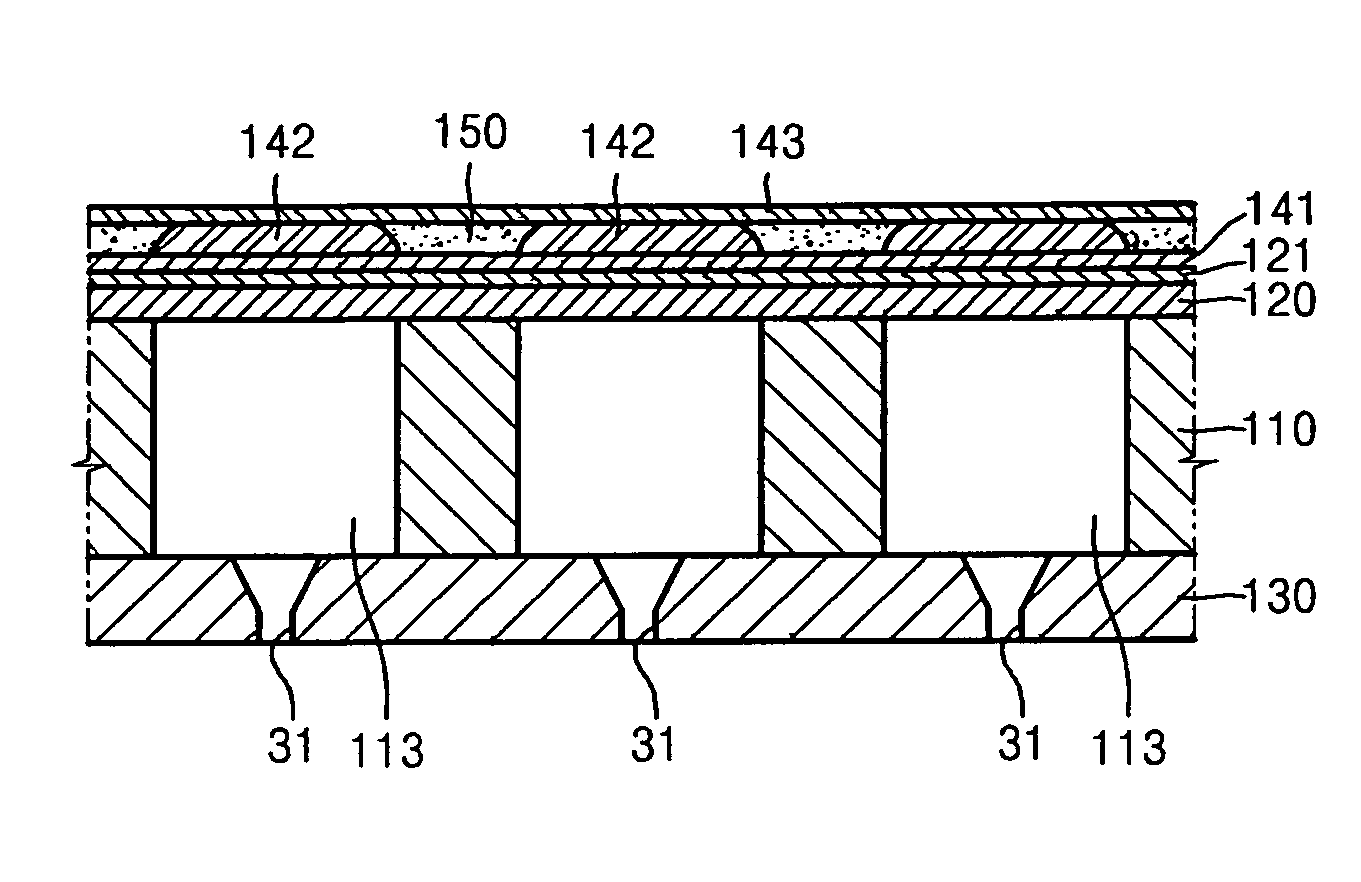
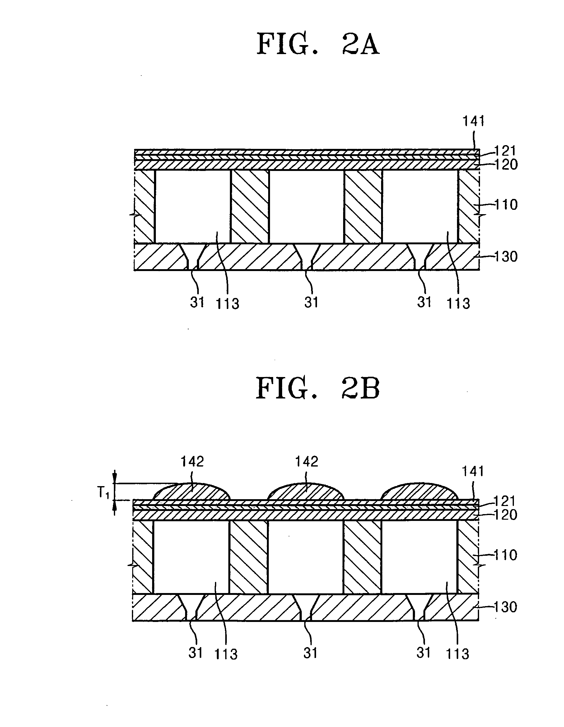
[0031]FIG. 2A through FIG. 2F are views sequentially illustrating a method of forming a piezoelectric actuator of an inkjet head according to an embodiment of the present general inventive concept. The drawings illustrate a part of the inkjet head, and generally, several tens or hundreds of pressure chambers and nozzles are arranged along one line or a plurality of lines in an inkjet head.

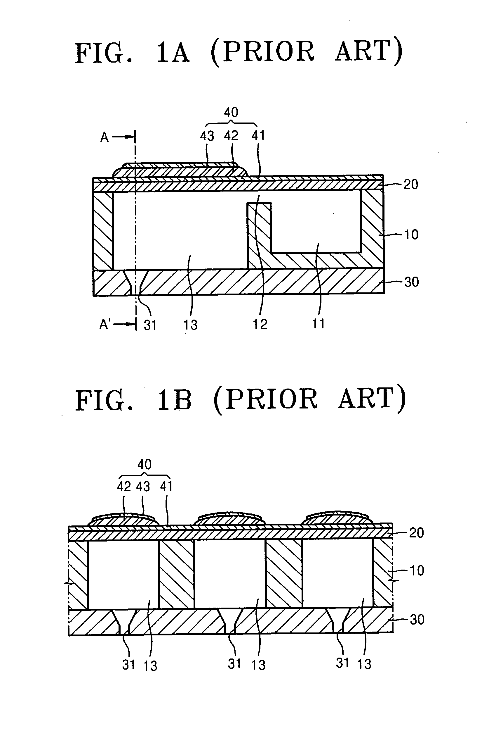
[0032]Referring to FIG. 2A, a piezoelectric inkjet head may include an ink flow channel, which may be formed on plates, for example, a flow channel plate 110, a vibrating plate 120, and a nozzle plate 130. A plurality of pressure chambers 113 a...


PUM

PropertyMeasurementUnit
thickness T2aaaaaaaaaa
temperatureaaaaaaaaaa

Abstract

A method of forming a piezoelectric actuator of an inkjet head formed on a vibrating plate to provide a driving power for ejecting ink to each of pressure chambers is provided. The method includes forming a lower electrode on a vibrating plate, forming a piezoelectric layer on the lower electrode to be located above each of pressure chambers, forming a protecting layer covering the lower electrode and the piezoelectric layer, exposing an upper surface of the piezoelectric layer by decreasing a thickness of the protecting layer and the piezoelectric layer, forming an upper electrode on the upper surface of the piezoelectric layer, removing the protecting layer. According to the present invention, since the piezoelectric layer having a flat upper surface is formed in uniform figure, area and thickness of the upper electrode formed thereon is uniformly controlled.

Description

CROSS-REFERENCE TO RELATED APPLICATIONS[0001]This application claims the benefit of Korean Patent Application No. 10-2006-0012598, filed on Feb. 9, 2006, in the Korean Intellectual Property Office, the disclosure of which is incorporated herein in its entirety by reference.BACKGROUND OF THE INVENTION[0002]1. Field of the Invention[0003]The present general inventive concept relates to an inkjet head, and more particularly, to a method of forming a piezoelectric actuator in a uniform shape, the piezoelectric actuator providing a driving force to eject ink from a piezoelectric inkjet head.[0004]2. Description of the Related Art[0005]Generally, inkjet heads are devices that can print a color image on a printing medium by ejecting droplets of ink onto a desired region of the printing medium. Depending on the ink ejecting method, the inkjet heads can be classified into two types: thermal inkjet heads and piezoelectric inkjet heads. The thermal inkjet head generates bubbles in the ink to b...

Claims


Application Information

Patent Timeline
Patent Type & Authority Applications(United States)
IPC IPC(8): H04R17/00B41J2/045B41J2/055B41J2/135B41J2/14B41J2/16H01L41/09H01L41/187H01L41/22H01L41/29H01L41/314H01L41/337H02N2/00
CPCB41J2/161B41J2/1631B41J2/1645Y10T29/435B41J2002/1425Y10T29/42Y10T29/49401B41J2/1646B41J2/045
Inventor LIM, SEUNG-MOLEE, KYO-YEOLCHUNG, JAE-WOOLEE, HWA-SUNLEE, JAE-CHANG
Owner SAMSUNG ELECTRO MECHANICS CO LTD
Why Eureka
Try Eureka