

Engine
- Summary
- Abstract
- Description
- Claims
- Application Information
AI Technical Summary
Benefits of technology
Problems solved by technology
Method used
Image

Examples
case 6
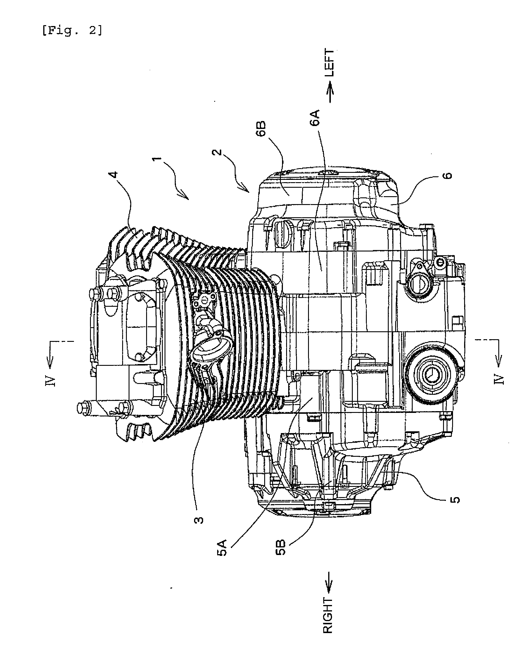
[0046] Left case 6 is also provided with a periphery wall 6A, a closing section 6B, and a partition wall 6C. Partition wall 6C divides left case 6 to form a generator chamber C that accommodates a generator, and a crank chamber D.
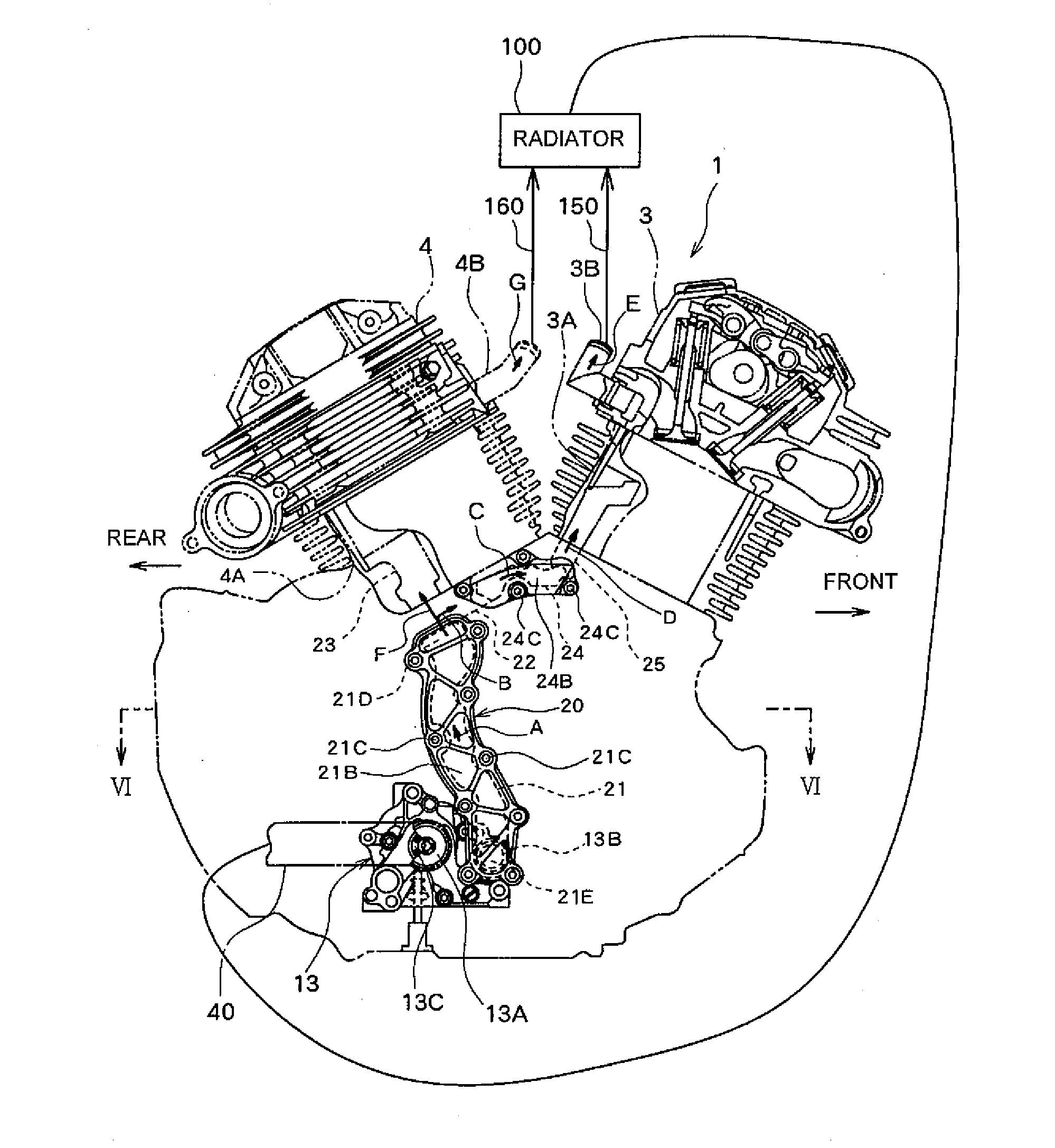
[0047] A main shaft 11 that is positioned toward a rear section of partition wall 5C is rotatably inserted in a bearing 5D that is a main shaft support portion inside right case 5. Clutch plate 10 is provided in an end section of main shaft 11, and clutch plate 10 is driven to rotate by driving force of engine 1 transmitted to main shaft 11. A crank shaft 12 that is positioned toward a front section of partition wall 5C is rotatably inserted in a bearing 5E that is a crank shaft support portion inside right case 5. Crank 101 accommodated in crank chambers B, D is integrally attached to an end section of crank shaft 12.
[0048] As seen in FIGS. 3 and 4, water pump 13 is provided inside crank chamber B of crank case 2 (at the rear surface side of partition wal...
PUM
 Abstract
Description
Claims
Application Information