Composite material placement method and system

a composite material and placement method technology, applied in the direction of process and machine control, mechanical control devices, instruments, etc., can solve the problems of increasing the size and complexity of the tape cutting device, wasting time and composite materials, and the cutting device is the least reliable component of the conventional laminating machin

Active Publication Date: 2007-08-16
THE BOEING CO
View PDF7 Cites 28 Cited by
  • Summary
  • Abstract
  • Description
  • Claims
  • Application Information

AI Technical Summary

Benefits of technology

[0006] An embodiment of the present invention relates to a method of applying a course on a layup mold. In this method, a ply boundary that defines a ply area on the layup mold is determined and a tape of composite material is applied on the ply area at an oblique angle relative to the ply boundary. In addition, a leading edge of the tape is butt cut and the leading edge and the ply boundary essentially converge. Furthermore, a trailing edge is generated. The trailing edge is a butt cut and the trailing edge and the ply boundary essentially converge.
[0007] Another embodiment of the present invention pertains to a method of fabricating a transition zone in a composite item. The transition zone defines an area that begins at a first skin gauge and ends at a second skin gauge. The transition zone includes a first oblique ply boundary that is offset from a second oblique ply boundary. In this method, a first set of tapes of composite material is applied across the first oblique ply boundary. Each of the first set of tapes includes a respective end that is butt cut and each of the first set of tapes includes a respective centerline. For each of the first set of tapes, the respective end and the respective centerline essentially converge upon the first oblique ply boundary. In addition, a second set of tapes of composite material is applied across the second oblique ply boundary. Each of the second set of tapes includes a respective end that is butt cut and each of the second set of tapes includes a respective centerline. For each of the second set of tapes, the respective end and the respective centerline essentially converge upon the second oblique ply boundary. The respective ends of the second set of tapes are offset from the respective ends of the first set of tapes to generate a crenulated pattern.
[0008] Yet another embodiment of the present invention relates to a computer readable medium on which is embedded computer software comprising a set of instructions for executing a method of applying a course on a layup mold. In this method, a ply boundary that defines a ply area on the layup mold is determined and a tape of composite material is applied on the ply area at an oblique angle relative to the ply boundary. In addition, a leading edge of the tape is butt cut and the leading edge and the ply boundary essentially converge. Furthermore, a trailing edge is generated. The trailing edge is a butt cut and the trailing edge and the ply boundary essentially converge.
[0009] Yet another embodiment of the present invention pertains to a computer readable medium on which is embedded computer software comprising a set of instructions for executing a method of fabricating a transition zone in a composite item. The transition zone defines an area that begins at a first skin gauge and ends at a second skin gauge. The transition zone includes a first oblique ply boundary that is offs

Problems solved by technology

However, increasing the width of the tape increases the size and complexity of the tape cutting device.
This procedure wastes

Method used


Image

  • Composite material placement method and system
  • Composite material placement method and system
  • Composite material placement method and system

Examples


Embodiment Construction

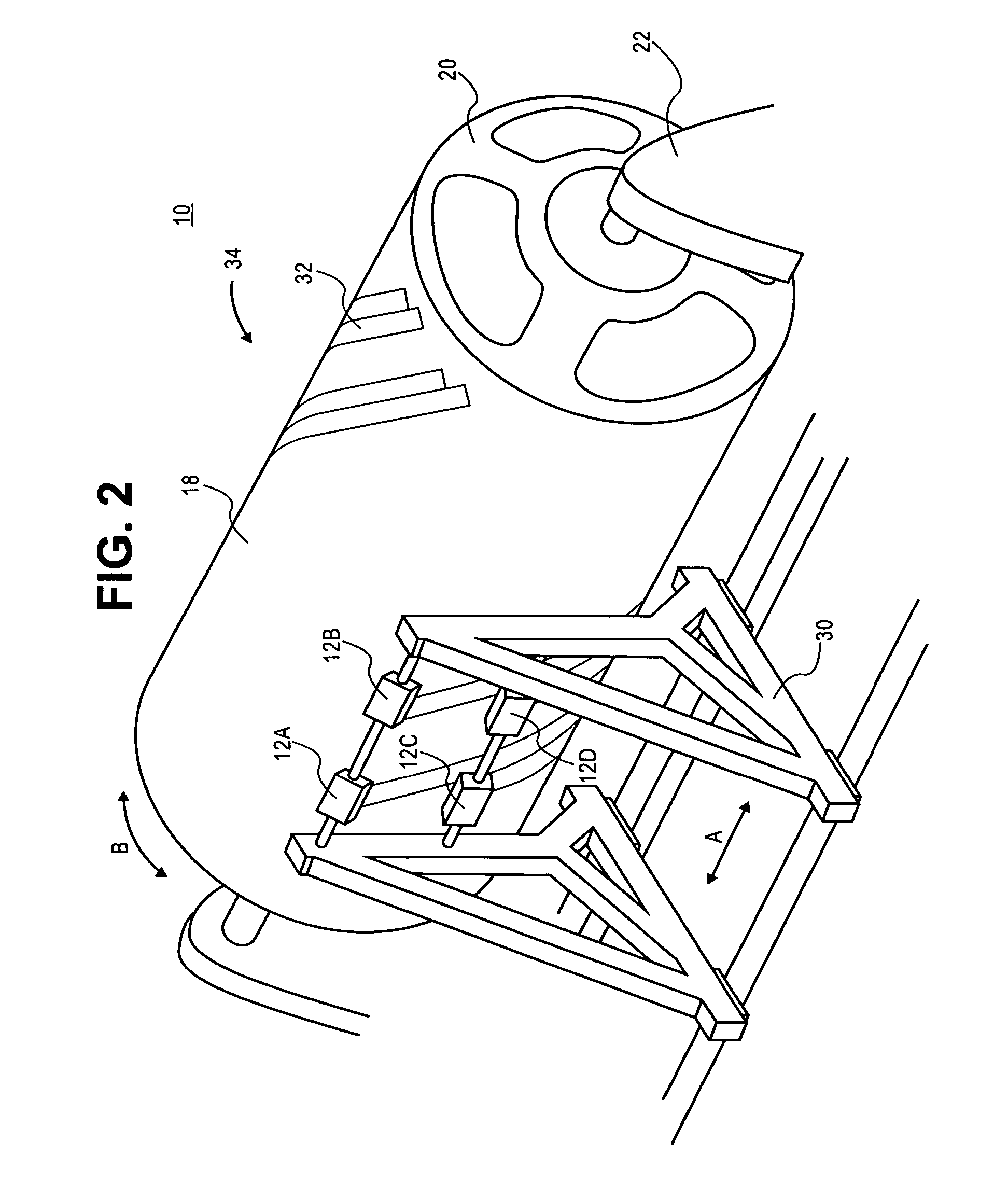
[0021] The present invention provides, in some embodiments, a system for placing plies to fabricate a composite item and a method of using this system. In various embodiments, the system includes an automated lamination device such as, for example, an automated fiber placement (AFP) machine, flat tape lamination machine (FTLM), numerically controlled (NC) contoured tape lamination machine (CTLM), multi-head tape lamination machine (MHTLM), and the like. This lamination device includes one or more dispensing heads to place plies of composite material upon a mandrel, layup mold or tool. In addition, the lamination device includes a cutting device to cut the composite material.

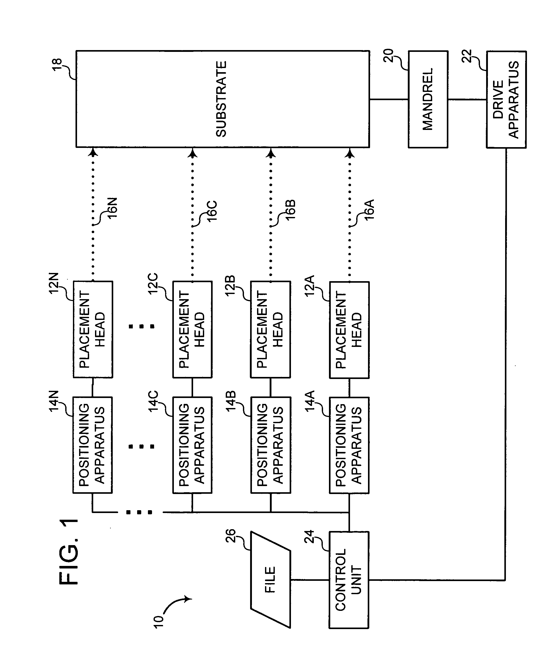
[0022] The invention will now be described with reference to the drawing figures, in which like reference numerals refer to like parts throughout. FIG. 1 is a block diagram of a multi-head tape lamination machine (MHTLM) 10 according to an embodiment of the invention. As shown in FIG. 1, the MHTLM 10 includes a ...


PUM

PropertyMeasurementUnit
Angleaaaaaaaaaa
Angleaaaaaaaaaa
Angleaaaaaaaaaa

Abstract

To apply a course on a layup mold, a ply boundary that defines a ply area on the layup mold is determined and a tape of composite material is applied on the ply area at an oblique angle relative to the ply boundary. In addition, a leading edge of the tape is butt cut and the leading edge, and the ply boundary essentially converge. Furthermore, a trailing edge is generated. The trailing edge is a butt cut and the trailing edge and the ply boundary essentially converge.

Description

FIELD OF THE INVENTION [0001] The present invention generally relates to a system and method of fabricating a composite item. More particularly, the present invention pertains to a system for auto lamination of a composite and its method of use. BACKGROUND OF THE INVENTION [0002] Composite items are typically fabricated from multiple layers or plies. These plies generally include a variety of materials such as carbon fiber, various other fibers, metal films or foils, and the like. In addition, the plies may be pre-impregnated (if fiber) or coated (if foil) with a resin and are often dispensed from a roll or spool. In roll form, the composite ply material is referred to as “tape” and may or may not include a backing layer. This backing generally prevents resin coated or pre-impregnated ply material (prepreg) from adhering to itself and aids in handling the tape as the tape is applied to the tool and the layup. The tape is applied to tool in a multitude of courses laid side by side to...

Claims


Application Information

Patent Timeline
IPC IPC(8): B32B37/00
CPCB29C70/32B29C70/386B29C70/545Y10T156/10Y10T156/17Y10T156/1052Y10T156/1062Y10T156/1077B29C2793/0027B29C2793/0081
Inventor JOHNSON, BRICE A.CARBERY, DAVID J.
Owner THE BOEING CO
Why Eureka
Try Eureka