Device for cutting slot-shaped seats in wells by hydro-sandblasting method

a technology of hydro-sandblasting and slot-shaped seats, which is applied in the field of mining, can solve the problems of inability to control the speed of perforator b>3/b> movement in the cutting process, difficulty in practical cutting slots with desired parameters, and inability to meet the requirements of the desired parameters, etc., to achieve the effect of simplifying the device, reducing the list of shortcomings, and enhancing the convenience, reliability and stability

Inactive Publication Date: 2007-08-16
DAVIDSON DRILLING
View PDF21 Cites 17 Cited by
  • Summary
  • Abstract
  • Description
  • Claims
  • Application Information

AI Technical Summary

Benefits of technology

[0018]It is an object of the invention to decrease the listed shortcomings, and na

Problems solved by technology

Practical cutting of slots with desired parameters is quite difficult technical task as it is performed in complex conditions of different rocks and temperatures, at great depths, in the presence of extractive product and/or washing fluids and with remote control only.
This connection is complicated in construction and contains waterproof chambers with cross-flow canals for viscous fluid, a piston, pipes connected with each other and the tubing string (hereinafter PCS) by mova

Method used


Image

  • Device for cutting slot-shaped seats in wells by hydro-sandblasting method
  • Device for cutting slot-shaped seats in wells by hydro-sandblasting method
  • Device for cutting slot-shaped seats in wells by hydro-sandblasting method

Examples


Embodiment Construction

)

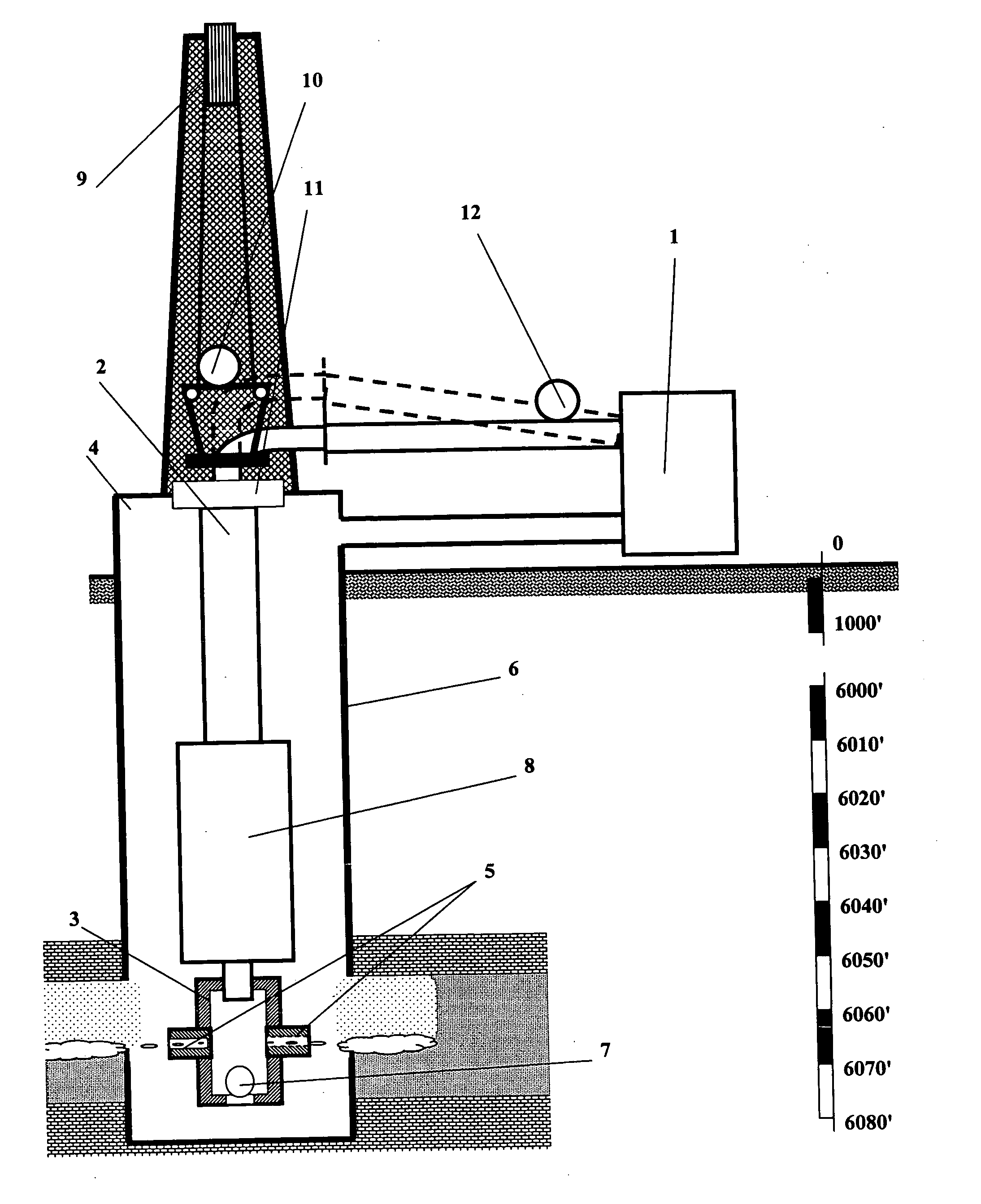
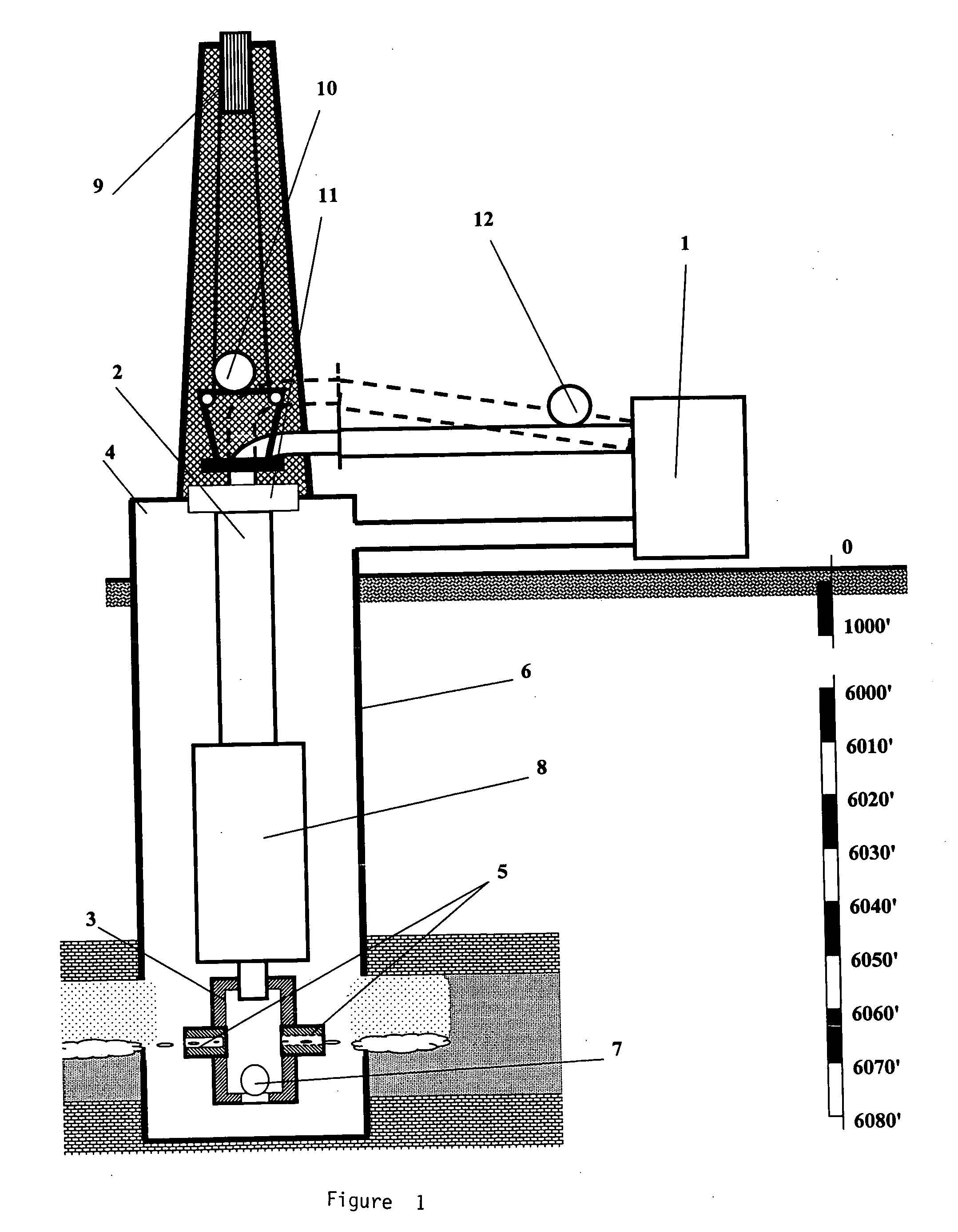
[0019]The determined task is solved by introducing essential changes into the known device for construction of cutting slot-shaped seats from the well wall inside the rock consisting of the hydro-abrasive jet generator connected with the perforator through the tubing string; the perforator is put into the casing pipe and has two diametrical nozzles which are directed at the well wall; there is a ball valve at the perforator end, as well as devices for adjustable partial unloading of PCS, PCS weight measuring device, abrasive jet pressure measuring device and the sealer for sealing of wellhead.

[0020]The changes are as follows:[0021]The perforator is directly connected with PCS;[0022]A pin mounted under the perforator with possible axial movements is introduced;[0023]A cylindrical retainer washer is put on the upper part of the perforator above nozzles; the washer is fixed so as to permit axial movement;[0024]PCS indexing mechanism, step rings and a tripping muff are mounted bottom u...


PUM


Abstract

This device relates to the fields of mining, specifically oil and gas industry, hydro-geological, geological engineering and water supply industries and is intended for cutting slot-shaped seats in well side zones of producing formation by hydro-abrasive blast. The determined task is solved by introducing essential changes into the known device for construction of cutting slot-shaped seats from the well wall inside the rock consisting of the hydro-abrasive jet generator connected with the perforator through the pump-and-compressor tubing string; the perforator is put into the casing pipe and has two diametrical nozzles which are directed at the well wall; there is a ball valve at the perforator end, as well as devices for adjustable partial unloading of PCS, PCS weight measuring device, abrasive jet pressure measuring device and the sealer for sealing of wellhead. The changes are as follows:—The perforator is directly connected with PCS;—A pin mounted under the perforator with possible axial movements is introduced;—A cylindrical retainer washer is put on the upper part of the perforator above nozzles; the washer is fixed so as to permit axial movement;—PCS indexing mechanism, step rings and a tripping muff are mounted bottom up and in alignment on the lower tube of PCS which is in series connected with the perforator;—At the same time the pin is connected with the cylindrical washer situated on the upper part of the perforator by control-rods with possible axial movement;—The indexing mechanism is put on PCS with the possibility of fixed coupling of its body with the casing pipe wall and split engagement of its body by step rings. Step rings are to be rigidly fixed on the lower PCS tube, and the tripping muff-on the PPS with its skirt down. At least a couple of rotary fluke-claws, with one end of each hingedly connected with the body of indexing mechanism, and the other end clasped to the casing pipe wall by spacer springs mounted between the indexing mechanism body and the fluke-flaw end, can be a variant of engagement of the indexing mechanism body with the casing pipe wall. At least a couple of spring-mounted pins installed on the interior surface of the indexing device body can be a variant of split engagement of the indexing mechanism by step rings. At that the pin heads are of round shape at the contacting end set against PCS. A muff with conical inside surface and the exterior of streamlined form can be a variant of tripping muff for forced tripping of the indexing mechanism from the casing pipe wall. The optimum distance between the step rings equals to one drain port diameter D±5%, and the number of rings has to amount to prescribed length of the slot-shaped seat divided by the drain port diameter D. At the same time adjacent drainage canals will unite and form a single slot-shaped seat. The recommended force for coupling of the split pin heads with PCS lies within the limits of 10-20% of PCS weight. The recommended force for coupling of the indexing device body with the casing pipe wall is in the range from 30% of PCS weight up to breaking strength point of the casing pipe.

Description

FIELD OF THE INVENTION[0001]This invention relates to the fields of mining, specifically oil and gas industry, hydro-geological, geological engineering and water supply industries and is intended for cutting slot-shaped seats in well side zones of producing formation by hydro-abrasive blast.BACKGROUND OF THE INVENTION[0002]Slot unloading of well side zones of producing formations is known as one of the most effective methods of enhancement of efficiency (productivity) of oil, gas, pumping, hydro-geological, geological engineering and water supply wells. This method provides for construction of slots in a well side zone which width, depth and orientation are predefined by known methods according to characteristics of the well and producing formation (e.g., see Reference bibliography in the end of the application). Practical cutting of slots with desired parameters is quite difficult technical task as it is performed in complex conditions of different rocks and temperatures, at great ...

Claims


Application Information

Patent Timeline
IPC IPC(8): E21B29/00
CPCE21B29/06E21B43/119E21B43/114
Inventor IVANOV, ANATOLY NIKOLAYEVICHIVANOV, ARTEM ANATOLYEVICHTICHONOV, ARTEM IVANOVICHPALTER, JAKEKEYSER, BORIS
Owner DAVIDSON DRILLING
Why Eureka
Try Eureka