
Convertible top with a rotational angle detection device

Inactive Publication Date: 2007-08-16
VALMET AUTOMOTIVE
View PDF17 Cites 6 Cited by
  • Summary
  • Abstract
  • Description
  • Claims
  • Application Information

AI Technical Summary

Benefits of technology

[0004]It is an object of the present invention to provide a folding convertible top having at least one simple-to-construct rotational angle detection device that requires minimal space.
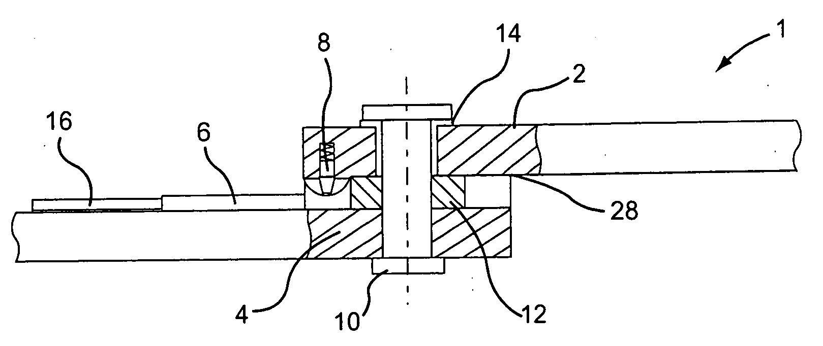
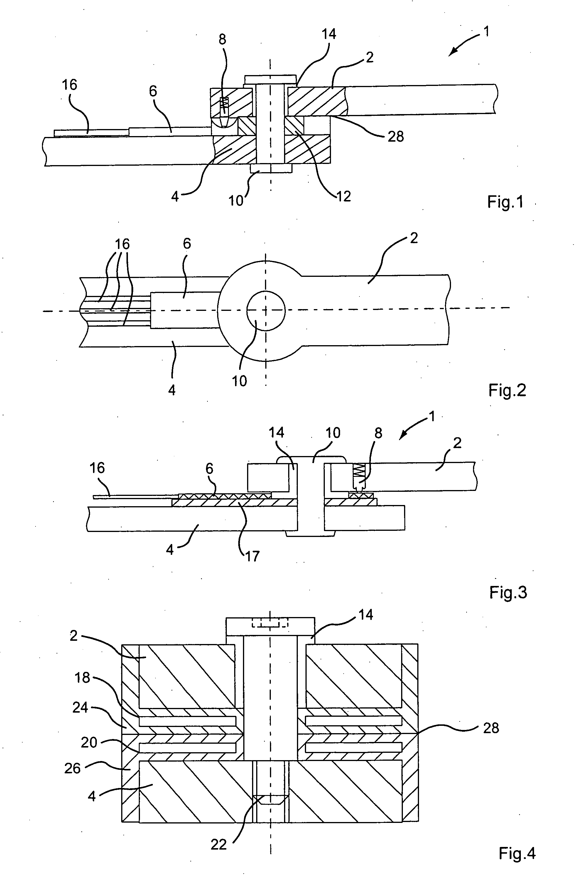
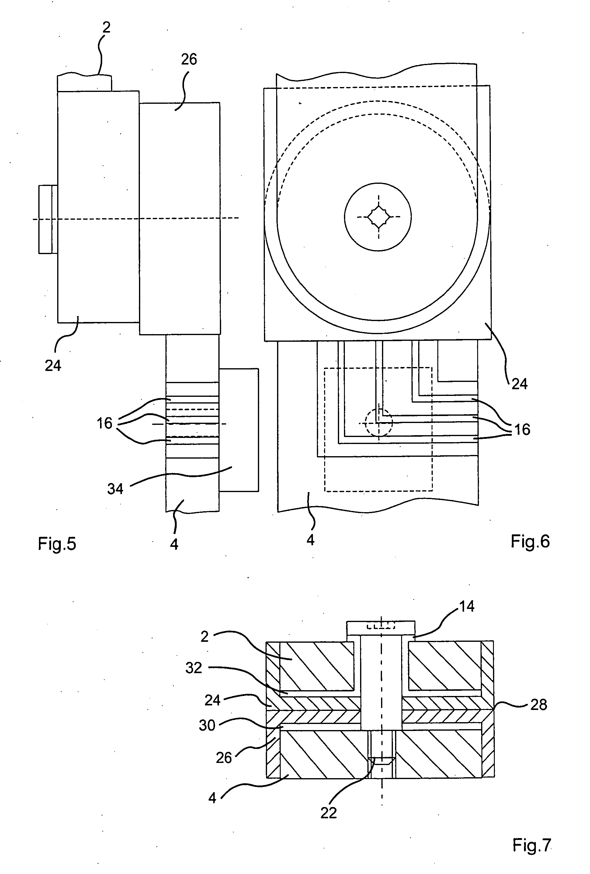
[0007]In addition or in the alternative, the rotary hinge may comprise a first housing part rotatably or pivotably coupled to a second housing part. The first and second housing parts are preferably coupled to the first and second linkage arms, respectively, so as to rotate therewith. For example, the first and second housing parts may be attached to end portions of the respective linkage arms. In addition, the rotational angle encoder may be disposed within the first or second housing part and the sensor element may be disposed in the other housing part. In such an embodiment, the rotational angle encoder and / or the sensor element are advantageously protected from damage and contamination while also minimizing overall space requirements for the rotational angle detection device.
[0014]In general, the present teachings provide a simple, inexpensive and reliable possibility for ascertaining the relative rotational or angular position of linkage arms, e.g. of a folding convertible top, wherein the installation space required by the device is small and the connection of the linkage arms, which form a rotary hinge, is realizable in a simple manner.

Problems solved by technology

By arranging the potentiometer coaxial to the rotational axis, the connection of the linkage arms is possible only with increased complexity due to the coaxial shaft of the potentiometer.
By laterally arranging the potentiometer adjacent to the rotary hinge, additional installation space is required, whereby the design possibilities for arranging the movable parts of the convertible top mechanism are restricted.

Method used


Image

  • Convertible top with a rotational angle detection device
  • Convertible top with a rotational angle detection device
  • Convertible top with a rotational angle detection device

Examples


Embodiment Construction

[0023]In the following description, three preferred embodiments of a rotary hinge 1 constructed from and pivotably connecting two linkage arms 2 and 4 will be described in an exemplary manner. The invention is limited neither to the number of linkage arms nor to detailed embodiments described herein. Furthermore, the invention is not limited to rotary hinges for folding convertible tops, as the present invention will find application in a variety of fields for which determination of the rotational angle of a rotary hinge is desirable.

[0024]It is expressly noted that each of the additional features and teachings disclosed above and below may be utilized separately or in conjunction with other features and teachings to provide improved convertible tops and rotational angle detection devices and methods for designing and using such convertible tops and rotational angle detection devices.

[0025]Representative examples of the present invention, which examples utilize many of these additio...


PUM


Abstract

A folding convertible top for a convertible vehicle includes a rotational angle detection device disposed in a rotary hinge (1) for detection of the rotational angle between linkage arms (2, 4) of a convertible top frame that are pivotably connected with each other by a bearing pin (10; 22). A rotational angle encoder (8; 18; 30) is connected with one linkage arm so as to rotate therewith and a sensor element (6; 20; 32) is connected with the other linkage arm so as to rotate therewith. The rotational angle encoder and / or the sensor element is / are disposed adjacent to the bearing pin on respective surfaces of the linkage arms facing towards each other or within housing parts (24, 26) connected to the respective linkage arms.

Description

CROSS-REFERENCE[0001]Priority to German patent application no. 10 2006 006 673.1 filed Feb. 14, 2006 is claimed, the contents of which are incorporated herein by reference in its entirety.TECHNICAL FIELD[0002]The invention concerns a convertible top for a convertible automobile that includes a rotational angle detection device for at least one rotary hinge (pivot point) in the linkage / frame assembly of the folding convertible top.BACKGROUND ART[0003]U.S. Pat. No. 5,225,747 describes a rotational angle detection device that measures the momentary angular position of a rotary hinge and supplies the measured data to a control unit. The rotational angle is detected by a potentiometer that is affixed substantially laterally adjacent to the rotary hinge in a sealed housing. By arranging the potentiometer coaxial to the rotational axis, the connection of the linkage arms is possible only with increased complexity due to the coaxial shaft of the potentiometer. By laterally arranging the pot...

Claims


Application Information

Patent Timeline
IPC IPC(8): B60J10/10B60J10/90
CPCG01D5/165B60J2007/1208B60J7/0573B60J7/1204
Inventor JAHN, JORGGUTENDORF, PETER
Owner VALMET AUTOMOTIVE
Learn More