
Methods and apparatus for generating strongly-ionized plasmas with ionizational instabilities

a technology of ionization instabilities and plasmas, which is applied in the direction of electrical equipment, light sources, electric discharge tubes, etc., can solve the problems of overheating the electrodes as well as the workpiece in the chamber, temperature gradients in the chamber, and overheating the workpi

Inactive Publication Date: 2007-08-16
ZOND
View PDF45 Cites 24 Cited by
  • Summary
  • Abstract
  • Description
  • Claims
  • Application Information

AI Technical Summary

Problems solved by technology

Applying high electrical currents through a plasma can result in overheating the electrodes as well as overheating the work piece in the chamber.
However, the cooling can cause temperature gradients in the chamber.
These temperature gradients can cause non-uniformities in the plasma density which can cause non-uniform plasma process.
However, pulsed DC power systems are prone to arcing at plasma ignition and plasma termination, especially when working with high-power pulses.
Arcing can result in the release of undesirable particles in the chamber that can contaminate the work piece.
However, the electrode voltage is limited in many applications because high electrode voltages can effect the properties of films being deposited or etched.
In addition, high electrode voltages can also cause arcing which can damage the electrode and contaminate the work piece.

Method used


Image

  • Methods and apparatus for generating strongly-ionized plasmas with ionizational instabilities
  • Methods and apparatus for generating strongly-ionized plasmas with ionizational instabilities
  • Methods and apparatus for generating strongly-ionized plasmas with ionizational instabilities

Examples


Embodiment Construction

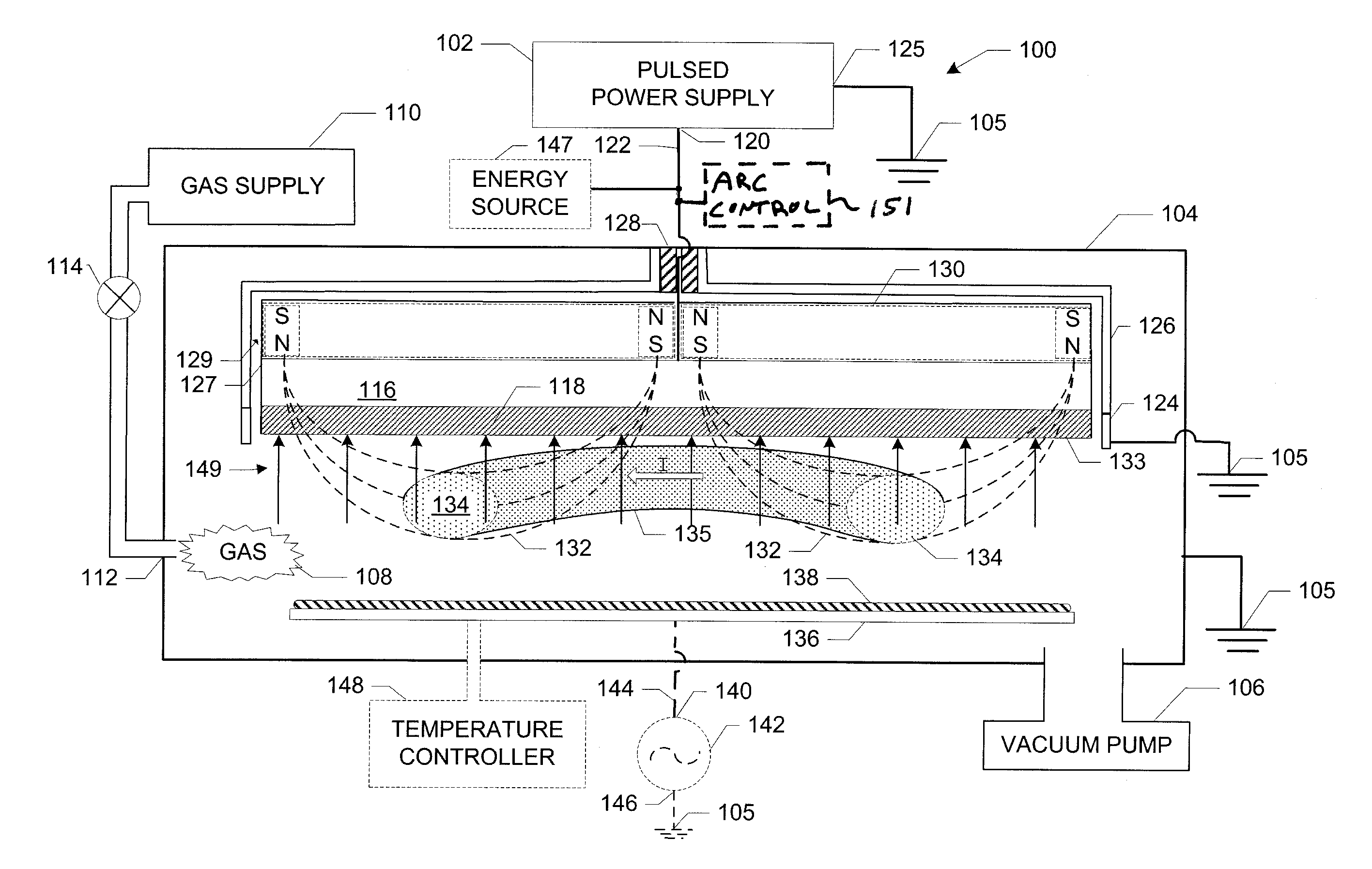
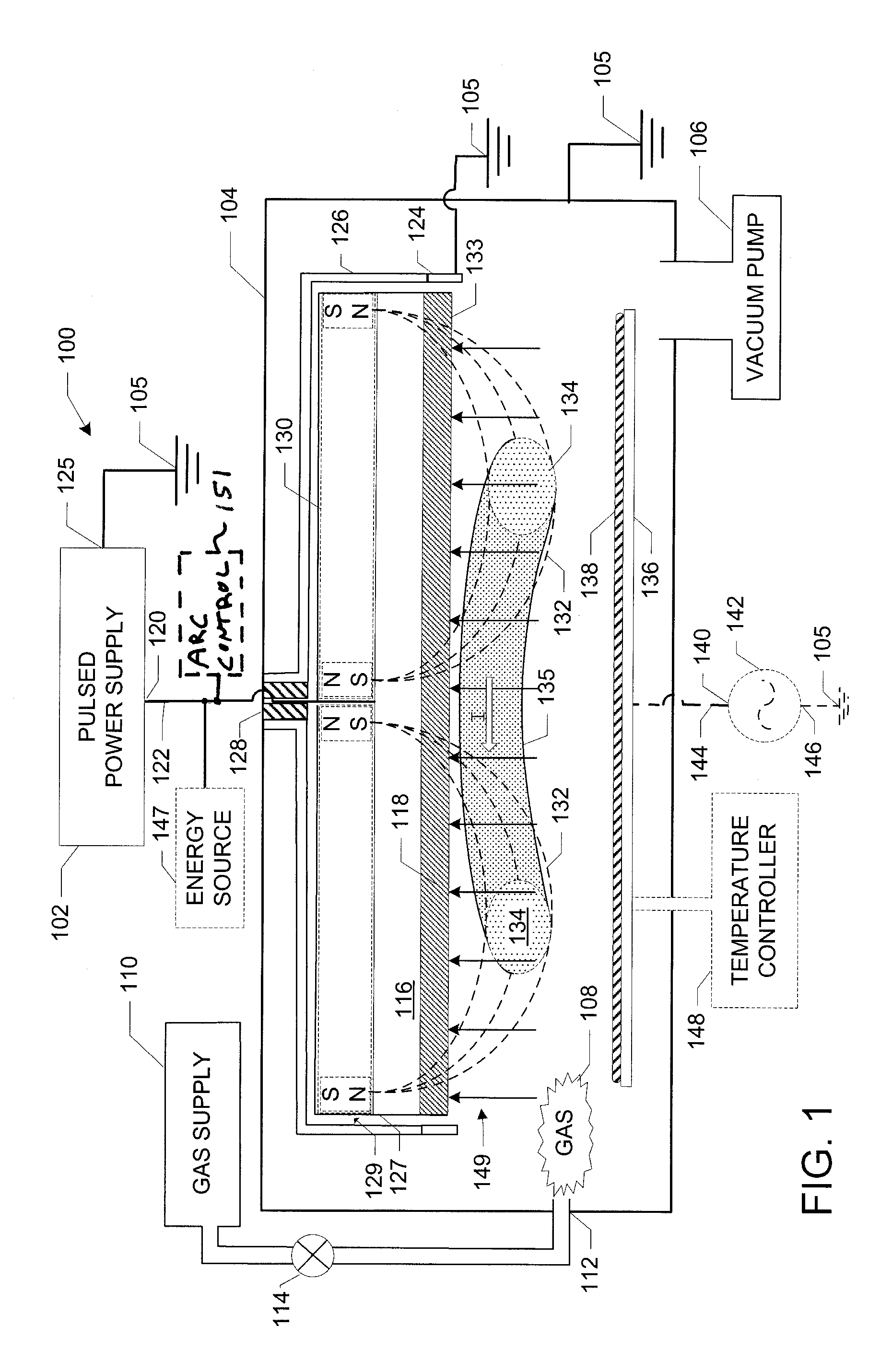
[0020]FIG. 1 illustrates a cross-sectional view of a plasma sputtering apparatus 100 having a pulsed direct current (DC) power supply 102 according to one embodiment of the invention. The plasma sputtering apparatus 100 includes a vacuum chamber 104 for containing a plasma. The vacuum chamber 104 can be coupled to ground 105. The vacuum chamber 104 is positioned in fluid communication with a vacuum pump 106 that is used to evacuate the vacuum chamber 104 to high vacuum. The pressure inside the vacuum chamber 104 is generally less than 10−1 Torr for most plasma operating conditions. A process or feed gas 108 is introduced into the vacuum chamber 104 through a gas inlet 112 from a feed gas source 110, such as an argon gas source. The flow of the feed gas is controlled by a valve 114. In some embodiments, the gas source is an excited atom or metastable atom source.

[0021] The plasma sputtering apparatus 100 also includes a cathode assembly 116. The cathode assembly 116 shown in FIG. 1 ...


PUM


Abstract

A strongly-ionized plasma generator includes a chamber for confining a feed gas. An anode is positioned inside the chamber. A cathode assembly is positioned adjacent to the anode inside the chamber. An output of a pulsed power supply is electrically connected between the anode and the cathode assembly. The pulsed power supply comprising solid state switches that are controlled by micropulses generated by drivers. At least one of a pulse width and a duty cycle of the micropulses is varied so that the power supply generates a multi-step voltage waveform at the output having a low-power stage including a peak voltage and a rise time that is sufficient to generate a plasma from the feed gas and a transient stage including a peak voltage and a rise time that is sufficient to generate a more strongly-ionized plasma.

Description

CROSS REFERENCE TO RELATED APPLICATIONS [0001] This patent application is a continuation-in-part of U.S. patent application Ser. No. 11 / 376,036, filed Mar. 15, 2006, entitled “Methods and Apparatus for Generating Strongly-Ionized Plasmas with Ionizational Instabilities,” which is a continuation of U.S. Pat. No. 7,095,179. This application also claims priority to U.S. Provisional Application Ser. No. 60 / 745,398, filed on Apr. 22, 2006, entitled “Method and Apparatus for Generating High-Density Plasma with Controlled Instability.” The entire disclosure of these patent applications and U.S. Pat. No. 7,095,179 are incorporated herein by reference.BACKGROUND OF THE INVENTION [0002] A plasma can be created in a chamber by igniting a direct current (DC) electrical discharge between two electrodes in the presence of a feed gas. The electrical discharge generates electrons in the feed gas that ionize atoms thereby creating the plasma. The electrons in the plasma provide a path for an electri...

Claims


Application Information

Patent Timeline
Patent Type & Authority Applications(United States)
IPC IPC(8): H01J7/24
CPCH01J37/32009H01J37/32045H01J2237/0206H01J37/3408H01J37/3444H01J37/3405
Inventor CHISTYAKOV, ROMANABRAHAM, BASSAM HANNA
Owner ZOND
Learn More