
System and method for displaying images

Inactive Publication Date: 2007-08-16
TEXAS INSTR INC
View PDF3 Cites 6 Cited by
  • Summary
  • Abstract
  • Description
  • Claims
  • Application Information

AI Technical Summary

Benefits of technology

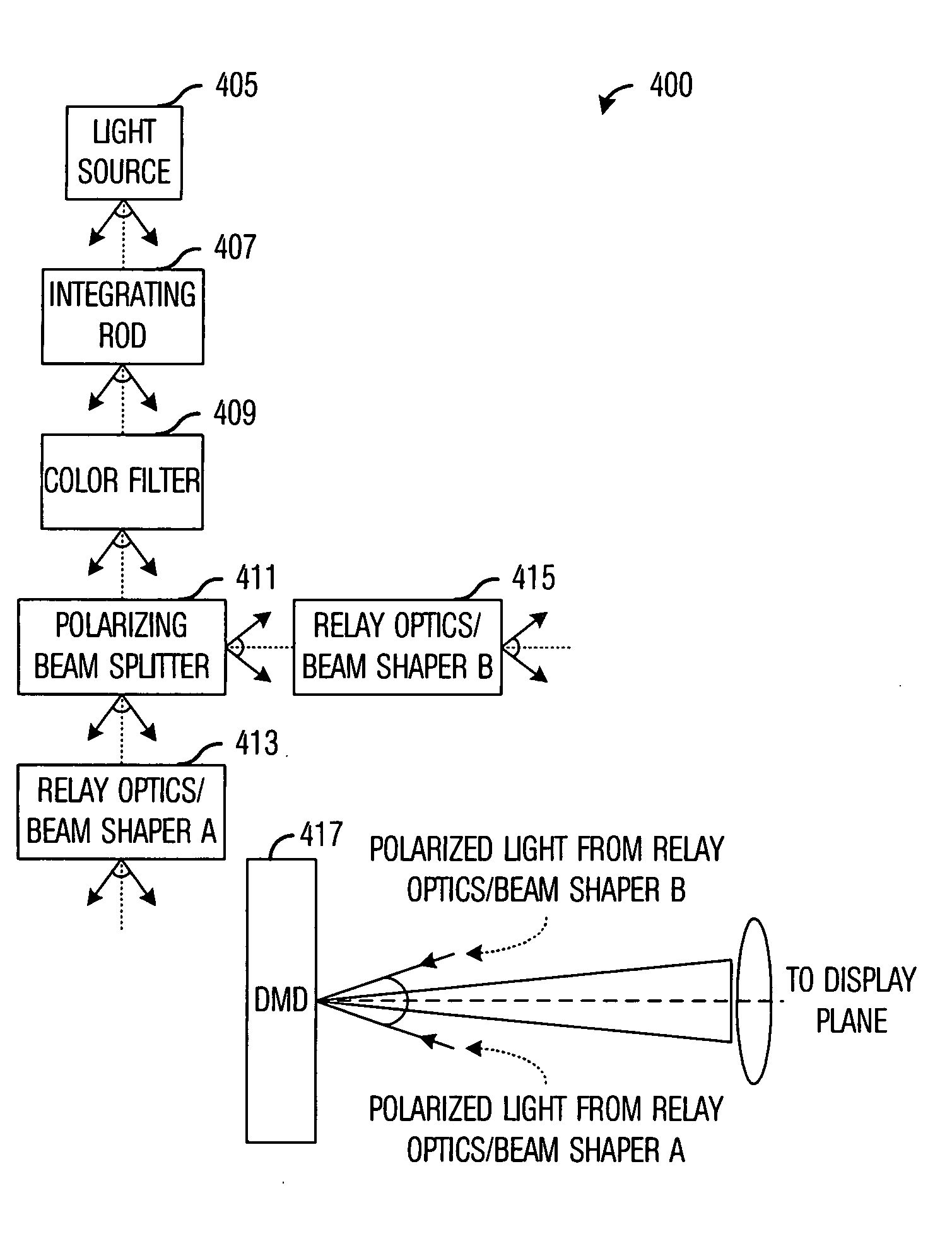
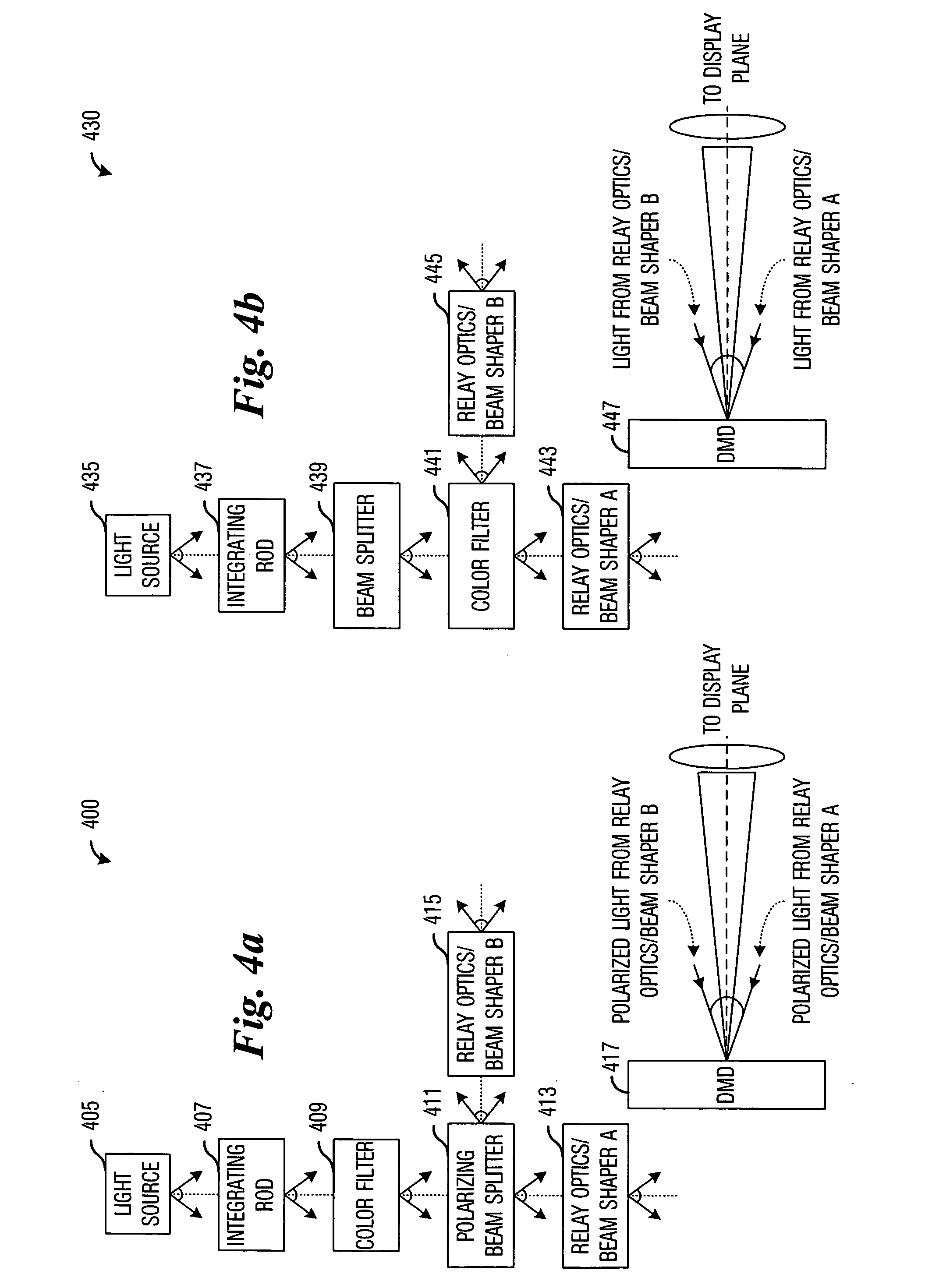
[0014] An advantage of a preferred embodiment of the present invention is that a single array of light modulators in a display system can be used to simultaneously display more than one image on a display plane. The use of a single array of light modulators can simplify the optical system in the display system. A simpler optical system can also be cheaper, therefore, the cost of the display system can be decreased.
[0015] A further advantage of a preferred embodiment of the present invention is that the use of the single array of light modulators can significantly reduce the cost of the optics and eliminate the need for frequent and expensive image alignment procedures. This can significantly reduce the operating cost of the display system.

Problems solved by technology

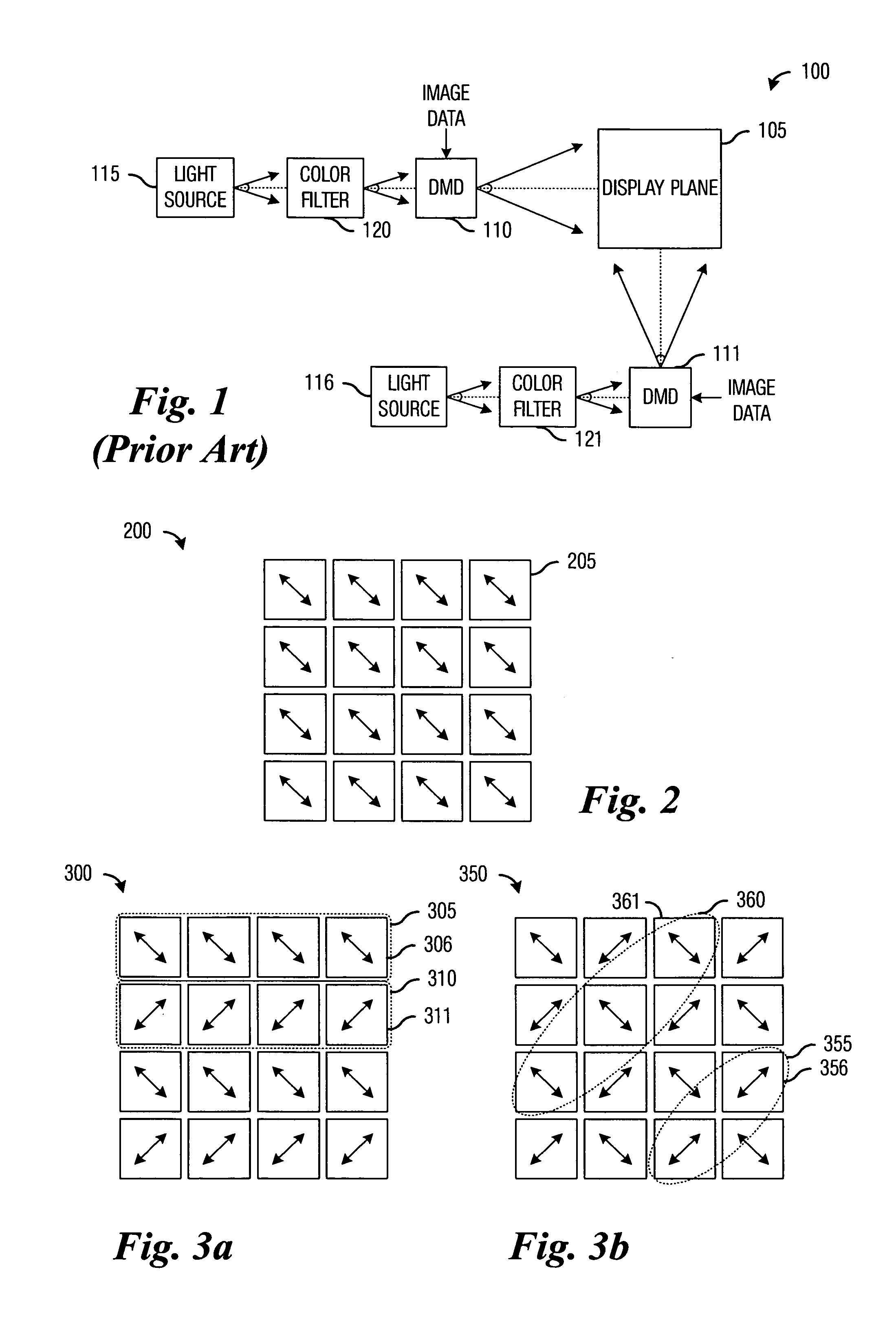
One disadvantage of the prior art is that with more than one separate projector or DMD, maintaining good alignment of the individual pixels can be very difficult.
A small bump to the display system can result in misalignment of the images produced by the display system.
Therefore, expensive optical components and regular calibration must be done regularly to ensure that the images remain aligned.
Furthermore, since separate projectors or DMDs are used, differences in thermal expansion may result in a misalignment of the images that occurs only after the display system has been powered for a period of time.
Another disadvantage of the prior art is that the optics required to combine the images from the separate projectors or DMDs can be prohibitively expensive.
Therefore the display systems that make use of separate projectors or DMDs are typically too expensive for all but high-end and commercial installations.

Method used


Image

  • System and method for displaying images
  • System and method for displaying images
  • System and method for displaying images

Examples


Embodiment Construction

[0025] The making and using of the presently preferred embodiments are discussed in detail below. It should be appreciated, however, that the present invention provides many applicable inventive concepts that can be embodied in a wide variety of specific contexts. The specific embodiments discussed are merely illustrative of specific ways to make and use the invention, and do not limit the scope of the invention.

[0026] The present invention will be described with respect to preferred embodiments in a specific context, namely a display system that can simultaneously display two images using a single array of light modulators, wherein the light modulators are positional micromirrors. The array of light modulators may be a part of a micro-electromechanical device. The two images can enable the use of stereoscopy to display 3-D images or the two images may display different color image data from a single image to help-mitigate color banding, rainbow effect, flicker, and so forth. The u...


PUM

PropertyMeasurementUnit
Polarityaaaaaaaaaa
Coloraaaaaaaaaa
Wavelengthaaaaaaaaaa

Abstract

System and method for simultaneous display of multiple images using a single light modulator array. A preferred embodiment comprises a light source that produces a light with desired spectral characteristics, a color filter optically coupled to the light source, and an array of light modulators optically coupled to the color filter. The color filter filters light from the light source to produce light of desired wavelengths and the array of light modulators simultaneously displays multiple images onto a display plane. Portions of the array of light modulators are designed so that each portion can independently display an image and the light source provides needed light to display the image.

Description

TECHNICAL FIELD [0001] The present invention relates generally to a system and a method for displaying images, and more particularly to a system and a method for the simultaneous display of multiple images using a single light modulator array. BACKGROUND [0002] In certain applications, there is a desire to display two (or more) images onto a single display plane of a display system. For example, in the projection of three dimensional (3-D) images using stereoscopy, two component images of a single three dimension image are displayed on the single display plane using polarized light with orthogonal polarizations. Audiences using special optical devices, such as 3-D glasses, can cancel out one of the two images per eye can then see a single 3-D image on the display plane. Additionally, it is possible to reduce color flicker and color banding on a display system if two (or more) images, each being displayed with a different colored light, were displayed simultaneously on a single displ...

Claims


Application Information

Patent Timeline
IPC IPC(8): G09G3/34G02B30/25
CPCG02B5/20G02B26/0841Y10T29/4913G09G3/003G09G3/346G09G3/002
Inventor MEHRL, DAVID JOSEPHMALINA, JAMES N.
Owner TEXAS INSTR INC
Learn More