Liquid detection device, liquid container and liquid ejection apparatus

a liquid detection device and liquid container technology, applied in the direction of printing, other printing apparatus, etc., can solve the problems of increasing the manufacturing cost of ink cartridges, inability to detect ink, etc., to achieve simple and reliably sealing, small vibration attenuation, and accurate detection

Inactive Publication Date: 2007-08-16
SEIKO EPSON CORP
View PDF2 Cites 19 Cited by
  • Summary
  • Abstract
  • Description
  • Claims
  • Application Information

AI Technical Summary

Benefits of technology

[0014] The invention has been finalized in view of the above problems, and it is an object of the invention to provide a liquid detection device that can simply and reliably perform sealing when a liquid detection device is attached to a container main body

Problems solved by technology

However, the method that manages ink consumption by the calculation of totalizing the number of ejections of the ink droplets or the ink amount using software has the following problems.
However, since the ink cartridge is filled with ink in an amount with a margin, taking into consideration of cumulative ink consumption errors due to the variations, there is a problem in that, in some cases, ink remains by the amount corresponding to the margin.
However, this method relies upon conductivity of ink in detecting the liquid level of ink, and thus it has a defect that kinds of detectable ink are limited or an electrode seal structure is complicated.
Further, the electrode usually uses a precious metal having good conductivity and high corrosion resistance, and thus manufacturing costs of the ink cartridge may be increased.
In addition, since two electrodes need to be attached, the number of manufacturing steps is increased, and thus manufacturing costs are

Method used


Image

  • Liquid detection device, liquid container and liquid ejection apparatus
  • Liquid detection device, liquid container and liquid ejection apparatus
  • Liquid detection device, liquid container and liquid ejection apparatus

Examples


first embodiment

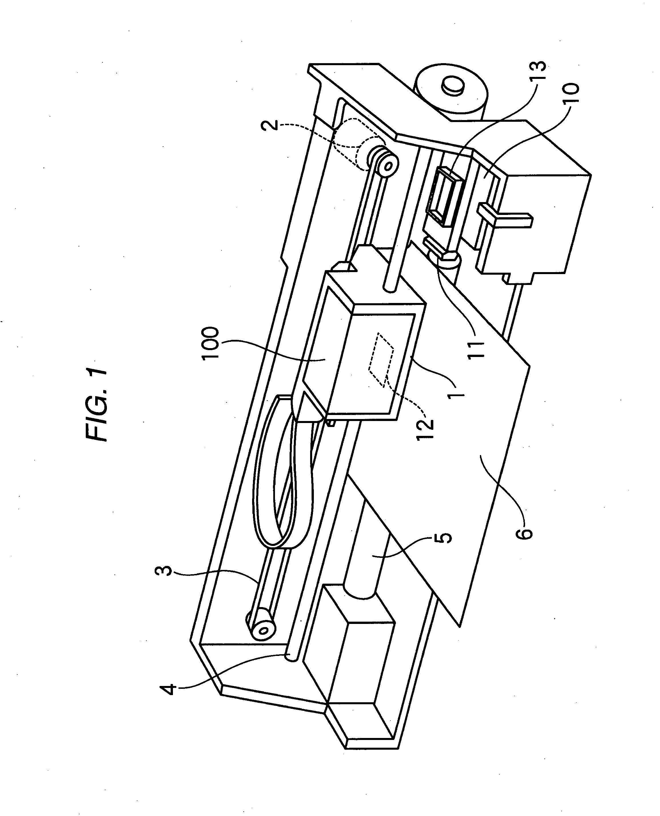
[0034]FIG. 1 shows the schematic configuration of an ink jet recording apparatus (liquid ejection apparatus) that uses an ink cartridge (liquid container) having a liquid detection device according to a In FIG. 1, reference numeral 1 denotes a carriage. The carriage 1 is guided by a guide member 4 and reciprocates in an axial direction of a platen 5 through a timing belt 3 that is driven by a carriage motor 2.

[0035] An ink jet recording head 12 is mounted on a side of the carriage 1 facing a recording paper 6, and an ink cartridge (liquid container) 100 that supplies ink to the recording head 12 is detachably mounted above the recording head 12.

[0036] A cap member 13 is disposed at a home position (a left side in the drawing) as a non-printing region of the recording apparatus. The cap member 13 is pressed into contact with a nozzle formation surface of the recording head 12 and forms a closed space with the nozzle formation surface when the recording head 12 mounted on the carria...

third embodiment

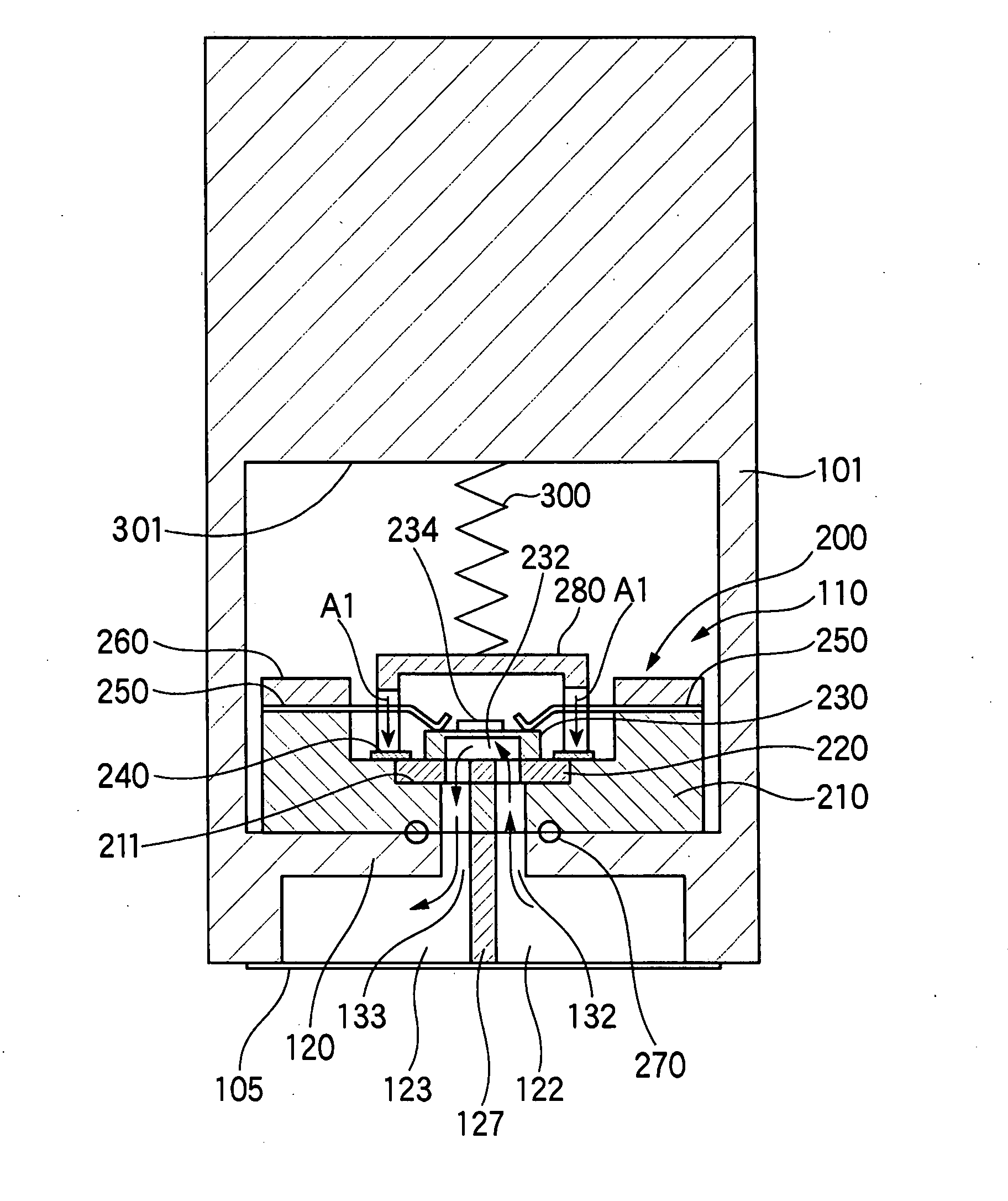
[0096]FIG. 8 is a diagram showing the operation of a liquid detection device 410 in the When the connection to the liquid consuming apparatus is made, the liquid detection device 410 has an opening 411 that is connected to the liquid containing portion 403 at the bottom, a liquid detection chamber 413 that is a cylindrical container having an opening 412 to be connected to the liquid supply port 405, a moving body 414 that moves according to the liquid level along the inner surface of the liquid detection chamber 413 and acts as one wall of the liquid detection chamber 413, a cover 415 that seals the opening of the liquid detection chamber 413 and has an air communicating path 415a for communicating an upper portion of the liquid detection chamber 413, that is, a spatial region to the air, a compressed spring 416 serving as an urging unit that is provided between the cover 415 and the moving body 414 to press the moving body 414 downward with a weak force, and a piezoelectric eleme...


PUM


Abstract

A liquid detection device that is accommodated in a sensor accommodating portion formed in a liquid container containing a liquid therein and detects the liquid in the liquid container using a piezoelectric element, wherein, when a wavelength of a vibration wave to be emitted from the piezoelectric element is λ, a distance H from a rear surface of a vibration wave emitting surface of the piezoelectric element to a wall surface facing the rear surface is represented by Equation 1.
(n×λ/2−λ/4−λ/8)≦H≦(n×λ/2−λ/4+λ/8)  (Equation 1)
(where n=1, 2, 3, . . . )

Description

BACKGROUND [0001] 1. Technical Field [0002] The present invention relates to a liquid detection device, and in particular, to a liquid detection device that is applied to a liquid ejection apparatus, such as an ink jet recording apparatus so as to primarily detect an ink residual quantity. [0003] 2. Related Art [0004] As a representative one of known liquid ejection apparatuses, there is an ink jet recording apparatus that has an ink jet recording head for image recording. Other liquid ejection apparatuses include, for example, an apparatus having a color material jetting head used in manufacturing color filters of a liquid crystal display or the like, an apparatus having an electrode material (conductive paste) jetting head used in forming electrodes of an organic electroluminescent (EL) display or a surface emission display (FED), an apparatus having a bioorganic compound jetting head used in manufacturing a bio-chip, an apparatus having a sample spraying head as a precision pipet...

Claims


Application Information

Patent Timeline
IPC IPC(8): B41J2/195B41J29/393B41J2/175
CPCB41J2/17513B41J2002/17583B41J2/17566B41J2/17553
Inventor ZHANG, JUNHUA
Owner SEIKO EPSON CORP
Why Eureka
Try Eureka