Charge neutralizer for glass substrate

a technology of neutralizer and glass substrate, which is applied in the direction of transportation and packaging, rigid containers, conveyors, etc., can solve the problems of no concrete description, increased charge electric potential, and rapid reduction of electrostatic capacity

Inactive Publication Date: 2007-08-16
FUTURE VISION
View PDF3 Cites 18 Cited by
  • Summary
  • Abstract
  • Description
  • Claims
  • Application Information

AI Technical Summary

Benefits of technology

[0012] In this respect, it is an object of the present invention to provide a charge neutralizer for neutralizing the glass substrate, by which it is possible to neutralize glass substrate by accurately irradiating a soft X ray into a narrow gap between the supporting means and the glass substrate immediately after the glass substrate is lifted up from the supporting means.
[0013] According to the present invention, optical axis of the soft X ray is accurately set into a gap between the glass substrate and the stage immediately after the glass substrate is lifted up from the table where the glass substrate is placed. For this purpose, adjusting means for adjusting mounting position of the soft X ray charge neutralizer and a soft X ray monitor for optical axis alignment are used. Also, under the condition not exceeding an allowable in-plane electric potential difference of the glass substrate or an allowable electric potential generated between the glass substrate and the earth in association with charge neutralizing conditions, the glass substrate is separated while the gap is widened, and it is advanced to the next process.
[0014] According to the present invention, it is possible to reliably neutralize by irradiating the soft X ray to the central portion of the transparent insulating substrate and to prevent electrostatic trouble, which may lead to the failure of the devices, under the condition that the charged electric potential does not exceed the allowable in-plane potential difference or the allowable electric potential value generated between the glass substrate and the earth immediately in the process that the glass substrate is lifting up from the table.

Problems solved by technology

However, there is no concrete description as to how soft X ray is irradiated into the gap between the earthed conductor and the glass substrate.
Also, when the glass substrate is lifted up too much, electrostatic capacity may be rapidly decreased and the charged electric potential may be increased, and this may cause troubles on the associated devices.
Also, there is no definite disclosure on concrete means to irradiate the soft X ray only on the electrically charged surface through the narrow gap when the separating distance is small.

Method used


Image

  • Charge neutralizer for glass substrate
  • Charge neutralizer for glass substrate
  • Charge neutralizer for glass substrate

Examples


example 1

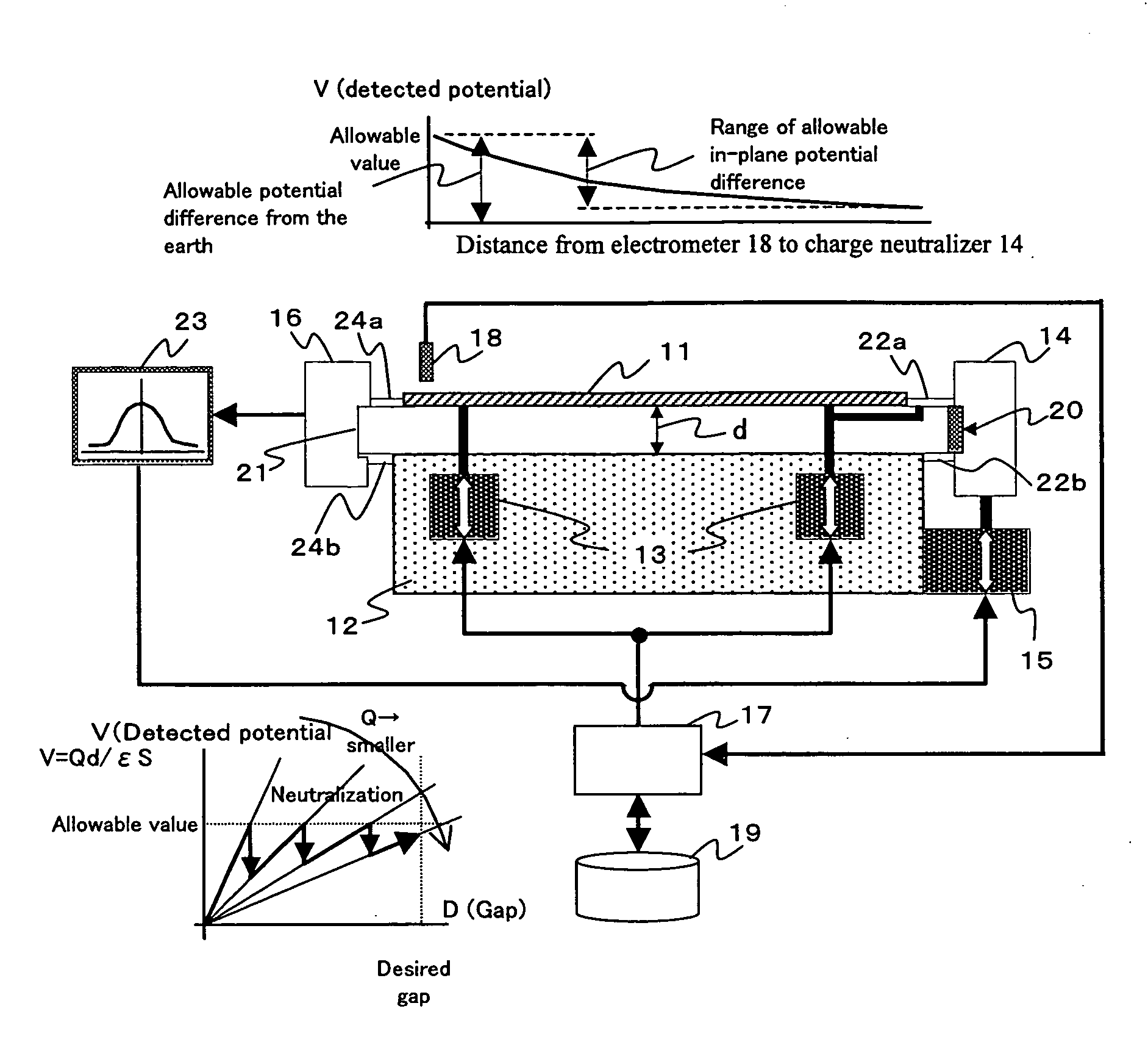
[0022]FIG. 1 represents diagrams and a drawing of a charge neutralizer for glass substrate according to the present invention. The charge neutralizer comprises a table 12 to place a glass substrate 11 on it, gap adjusting means 13 for separating the glass substrate 11 from the table 12 in order to send it to subsequent processes, a soft X ray charge neutralizer 14 for neutralizing rear side of the glass substrate 11 by, mounting position adjusting means 15 for aligning optical axis of the soft X ray charge neutralizer 14 to central position of a gap “d”, a soft X ray optical axis monitor 16 provided with a detection sensor for adjusting the optical axis, a control unit 17 for controlling the gap adjusting means 13, an electrometer 18 for measuring charged electric potential of the glass substrate 11, and a database 19 for storing an in-plane potential difference value or an allowable potential value corresponding to a height to lift up the glass substrate 11 from the table 12.

[0023...

example 2

[0035] As described above, it may be designed in such manner that the control unit 17 controls the gap adjusting means 13 according to the information from the database 19. In the present example, the gap “d” may be controlled by the gap adjusting means 13 by judging the neutralizing conditions as to whether the charged electric potential measured by the electrometer 18 is within the allowable value of the control unit 17 or not. In this case, it should be controlled in such manner that the electrometer 18 is installed at an end or at the center of the substrate where the charged electric potential is higher and that one of the potential values does not exceed the allowable value.

[0036] In the above, description has been given on the features of the present invention, while the soft X ray cannot be irradiated to the rear side of the glass substrate unless optical axis of the soft X ray irradiated from the charge neutralizer does not pass through the predetermined gap, and effective...


PUM


Abstract

The present invention provides a charge neutralizer for accurately irradiating a soft X ray into a narrow gap after a glass substrate is lifted up.
A soft X ray is introduced into a gap “d” from a soft X ray charge neutralizer 14, and the soft X ray is detected by a soft X ray optical axis monitor 16. Mounting position adjusting means 15 is adjusted by a detection output from said soft X ray optical axis monitor, and optical axis alignment is performed. Next, according to information from a database 19, a control unit 17 controls gap adjusting means 13, and charge neutralization is performed. Charge neutralization can also be performed by controlling the gap “d” by the gap adjusting means 13 while judging neutralizing conditions as to whether a charged potential measured by an electrometer 18 is within an allowable value by the control unit 17 or not.

Description

FIELD OF THE INVENTION [0001] 1. Technical Field [0002] The present invention relates to a charge neutralizer for a transparent insulating substrate such as a glass substrate. In particular, the invention relate to a charge neutralizer suitable for processes of film deposition or patterning on a glass substrate in the manufacture of a display panel for a liquid crystal display device. [0003] 2. Background Art [0004] In the processes of film deposition, patterning process, or transport of a transparent insulating substrate (hereinafter referred as “glass substrate”) for a display panel such as a liquid crystal display device, the glass substrate is electrically charged by static electricity. Such electric charge causes troubles on devices, e.g. thin-film transistor, formed on the glass substrate, resulting in the reduction of product reliability or in lower production yield. To eliminate these troubles, charge neutralization is performed on the glass substrate by using a charge neutr...

Claims


Application Information

Patent Timeline
Patent Type & Authority Applications(United States)
IPC IPC(8): H02H1/00
CPCB65G49/061H05K9/0067H05F3/06B65G2249/02B65D17/4012B65D17/502B65D51/245B65D2517/0098
Inventor INABA, HITOSHIFUJINO, MASAHARUFUKUCHI, YASUHIKONAKAJIMA, KAZUYOSHIKOCHI, MASATO
Owner FUTURE VISION
Why Eureka
Try Eureka