Random data compression scheme in a network diagnostic component

a network diagnostic and compression scheme technology, applied in data switching networks, frequency-division multiplexes, instruments, etc., can solve the problems of increased size, speed and complexity, difficult diagnosis and resolution, and demand for communication bandwidth

Active Publication Date: 2007-08-16
VIAVI SOLUTIONS INC
View PDF52 Cites 21 Cited by
  • Summary
  • Abstract
  • Description
  • Claims
  • Application Information

AI Technical Summary

Benefits of technology

[0007]Embodiments disclosed herein relate to a network diagnostic device or component that is placed in-line between two nodes in a network to compress a random data signal. For example, in one embodiment the network diagnostic component receives a random data signal from a first node for communication with a second node. The random data signal includes at least one or more random data units that represent a first data unit.

Problems solved by technology

Computer and data communications networks continue to proliferate due to declining costs, increasing performance of computer and networking equipment, and increasing demand for communication bandwidth.
As communication networks have increased in size, speed and complexity however, they have become increasingly likely to develop a variety of problems that, in practice, have proven difficult to diagnose and resolve.
The problems generally experienced in network communications can take a variety of forms and may occur as a result of a variety of different circumstances.
Examples of circumstances, conditions and events that may give rise to network communication problems include the transmission of unnecessarily small frames of information, inefficient or incorrect routing of information, improper network configuration and superfluous network traffic, to name just a few.
Such problems are aggravated by the fact that networks are continually changing and evolving due to growth, reconfiguration and introduction of new network topologies and protocols.

Method used


Image

  • Random data compression scheme in a network diagnostic component
  • Random data compression scheme in a network diagnostic component
  • Random data compression scheme in a network diagnostic component

Examples


Embodiment Construction

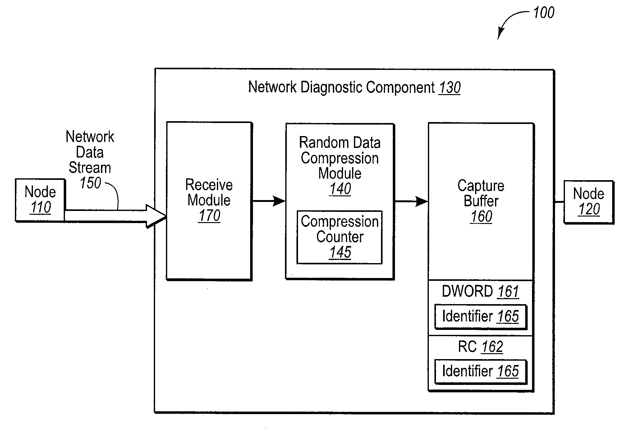
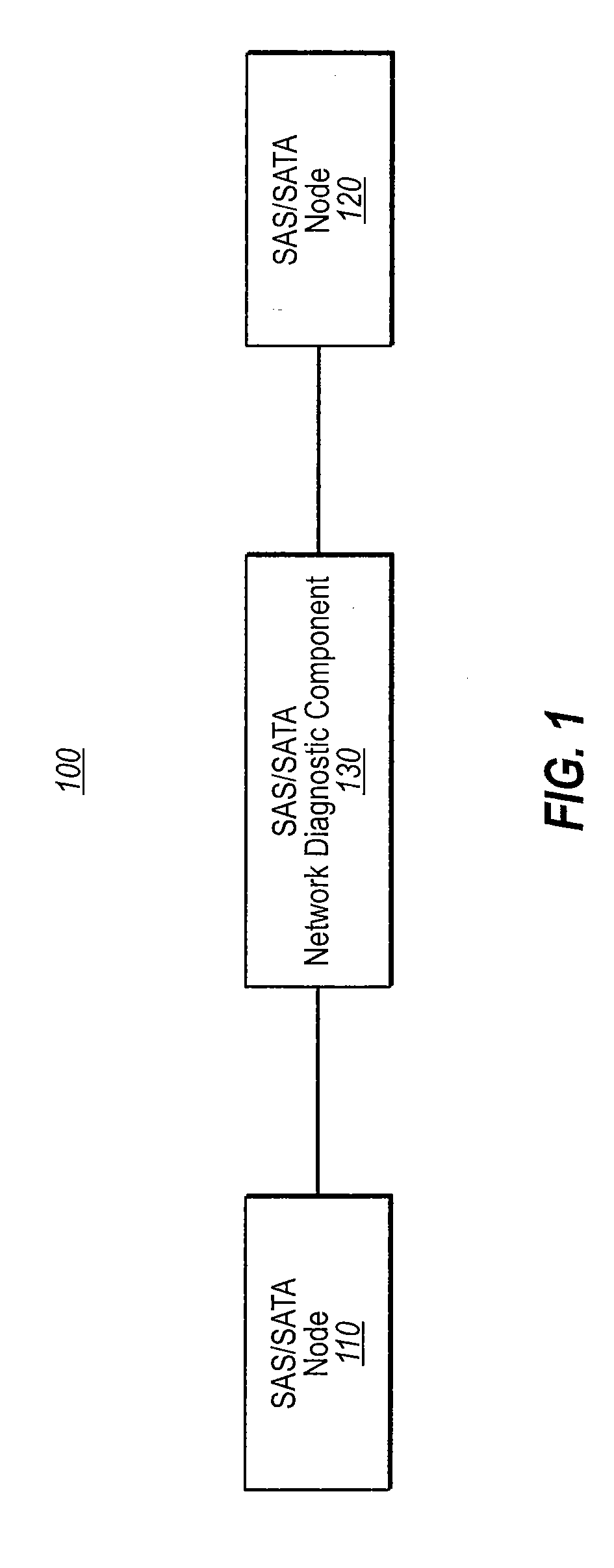
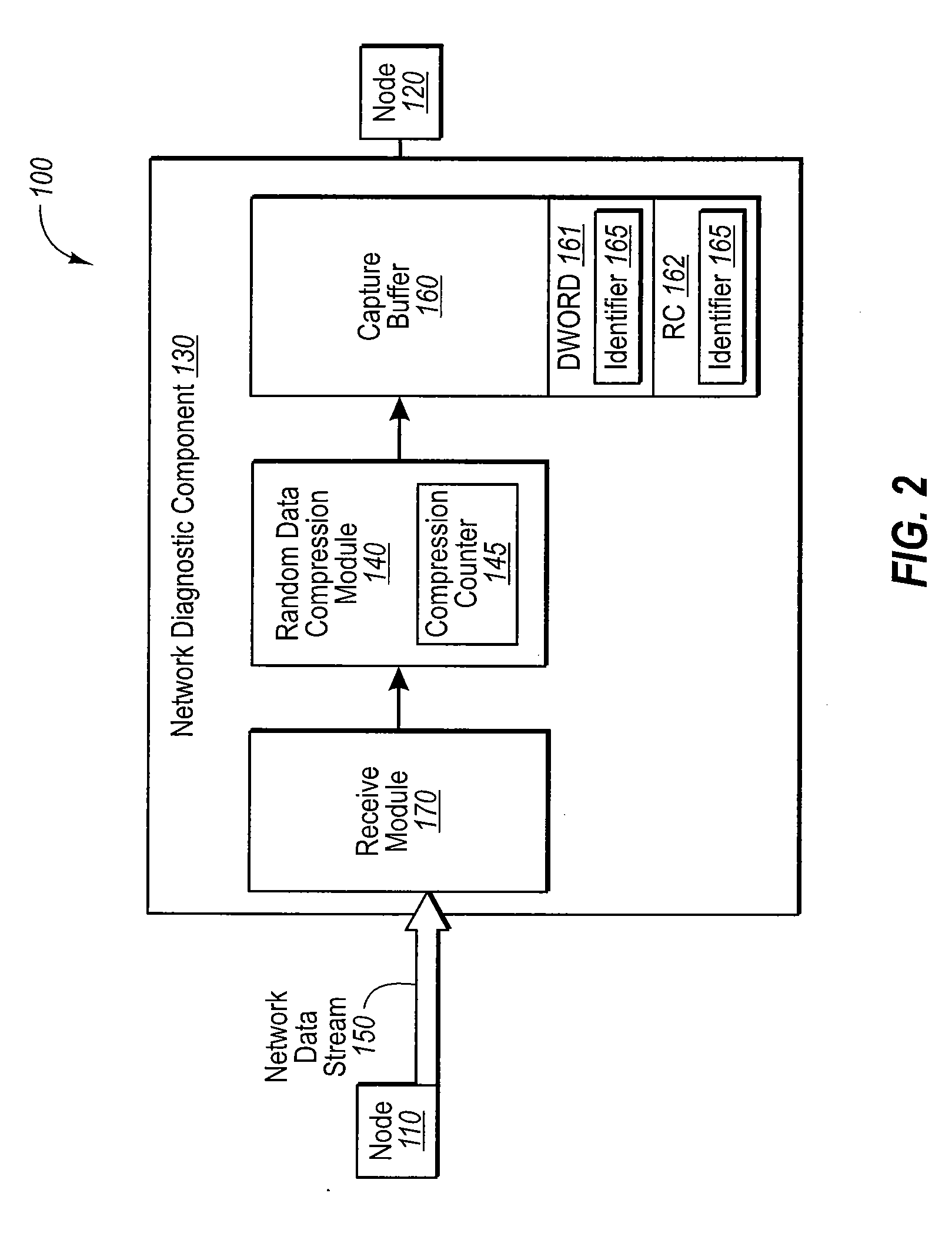
[0017]The embodiments disclosed herein relate to a network diagnostic component or device that is placed in-line between a first and second node of a network. The diagnostic component or device is used to compress a random data signal. For example, the first node may communicate with the second node using a random data signal that includes random data units that represent a first data unit. In some embodiments, the random data signal may be of the SAS / SATA protocol. The network diagnostic component may receive the random data signal and associate at least one random data unit with identifier that is indicative of the first data unit. This random data unit may be recorded in a memory. A representation of the random data units that are different from the random data unit associated with the identifier is also recorded in the memory.

[0018]The embodiments disclosed herein may be practiced in networking systems, including the testing of high speed data transmission systems and components...


PUM


Abstract

A network diagnostic component or device that is placed in-line between a first and second node. The diagnostic component or device is used to compress a random data signal. For example, the first node may communicate with the second node using a random data signal that includes random data units that represent a first data unit. In some embodiments, the random data signal may be of the SAS/SATA protocol. The network diagnostic component may receive the random data signal and associate at least one random data unit with identifier that is indicative of the first data unit. This random data unit may be recorded in a memory. A representation of the random data units that are different from the random data unit associated with the identifier is also recorded in the memory.

Description

CROSS-REFERENCE TO RELATED APPLICATIONS[0001]This application claims the benefit of U.S. Provisional Application No. 60 / 773,473, filed Feb. 14, 2006, which is incorporated herein by reference in its entirety.BACKGROUND[0002]Computer and data communications networks continue to proliferate due to declining costs, increasing performance of computer and networking equipment, and increasing demand for communication bandwidth. Communications networks—including wide area networks (“WANs”), local area networks (“LANs”), metropolitan area networks (“MANs”), and storage area networks (“SANS”)—allow increased productivity and use of distributed computers or stations through the sharing of resources, the transfer of voice and data, and the processing of voice, data and related information at the most efficient locations. Moreover, as organizations have recognized the economic benefits of using communications networks, network applications such as electronic mail, voice and data transfer, host ...

Claims


Application Information

Patent Timeline
Patent Type & Authority Applications(United States)
IPC IPC(8): H04L12/26
CPCH04L43/00H04L12/2602
Inventor MILNE, ANDREW J.GARCIA, ROUMEL R.GENTIEU, PAUL R.HIBBERT, GEOFFEY T.
Owner VIAVI SOLUTIONS INC
Why Eureka
Try Eureka