Methods and systems for transporting wind turbine components

a technology for wind turbine components and transportation methods, applied in transportation and packaging, transportation items, machines/engines, etc., can solve problems such as transportation costs

Inactive Publication Date: 2007-08-16
GENERAL ELECTRIC CO
View PDF20 Cites 103 Cited by
  • Summary
  • Abstract
  • Description
  • Claims
  • Application Information

AI Technical Summary

Benefits of technology

[0006]In one aspect, a mounting system for at least one of supporting and transporting a unitary load is provided. The mounting system includes a plurality of adjacent railcars including a first railcar having spaced first and second wheel assemblies each including at least one wheel pair. The mounting system also includes a first frame coupled to the first railcar. The first frame has a space defined between at least two portions of the first frame and at least one cushion selectively positionable within the first frame space. The mounting system also includes a separate second frame coupled to the first railcar. The second frame has a space defined between at least two portions of the second frame and at least one cushion selectively positionable within the second frame space. The second frame is spaced from the first frame to facilitate at least one of partially containing and partially supporting the load. The first frame is substantially centered over the at least one wheel pair of the first wheel assembly, and the second frame is substantially centered over the at least one wheel pair of the second wheel assembly.
[0007]In another aspect, a method for at least one of supporting and transporting at least one unitary load is provided. The method includes providing a plurality of adjacent railcars

Problems solved by technology

As a result, such known transportation methods and systems also facilitate increasing assoc

Method used


Image

  • Methods and systems for transporting wind turbine components
  • Methods and systems for transporting wind turbine components
  • Methods and systems for transporting wind turbine components

Examples


Embodiment Construction

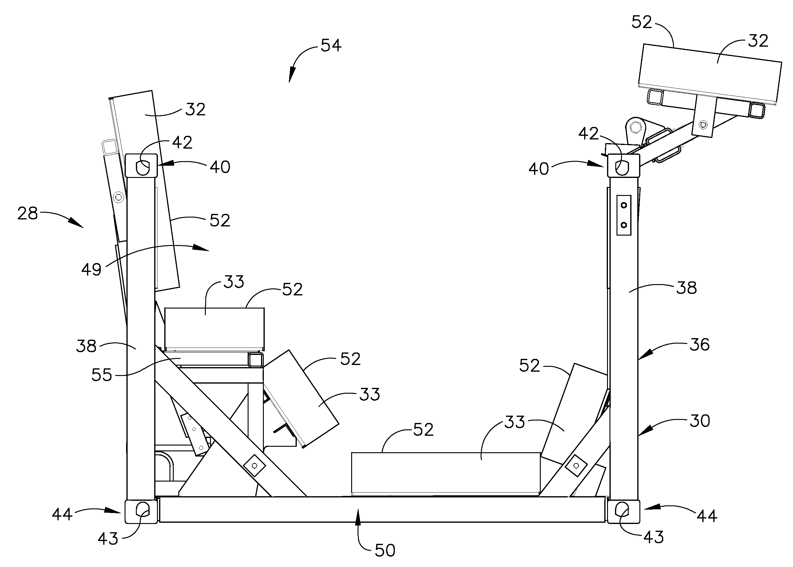
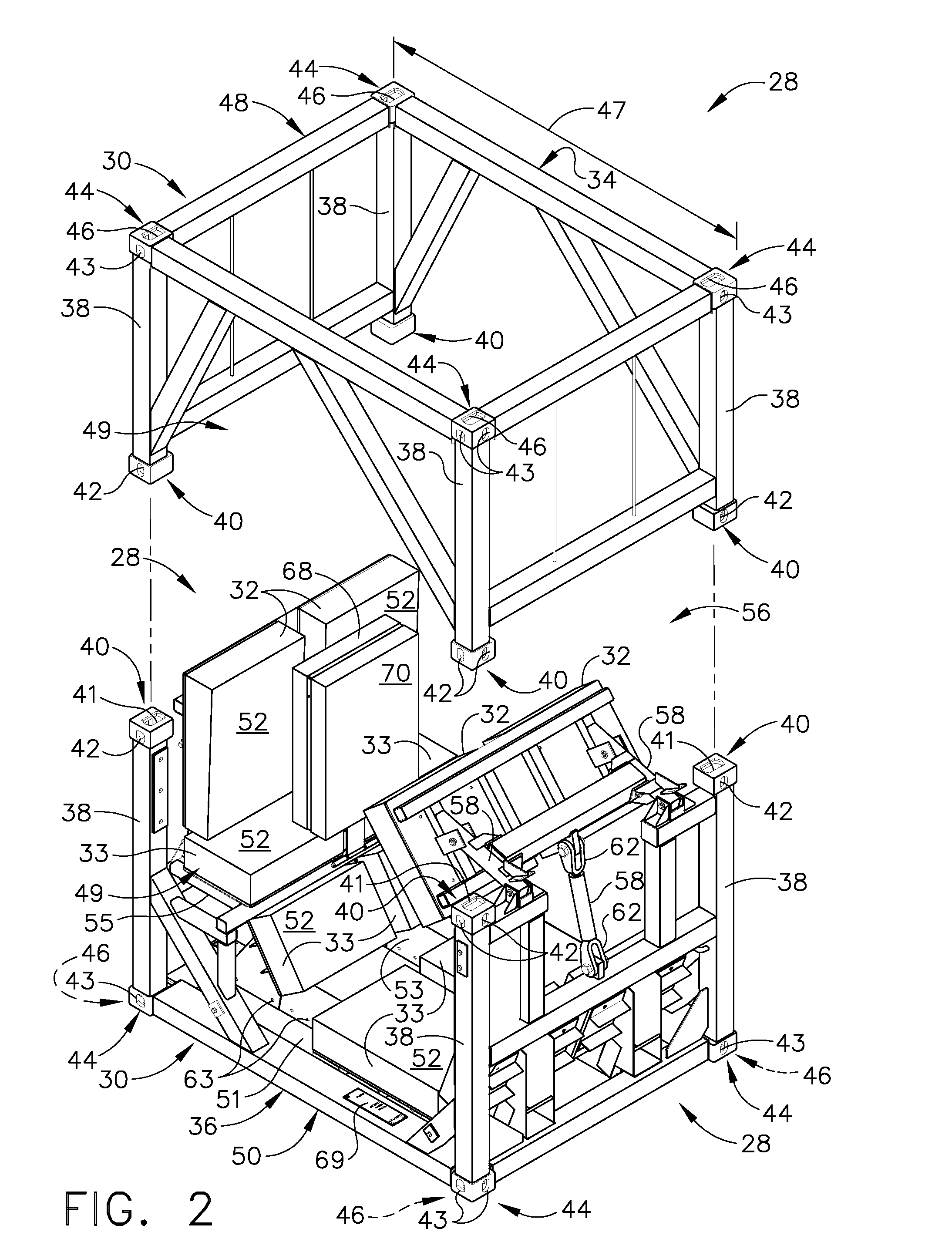
[0019]The exemplary methods and apparatus described herein overcome the disadvantages of at least some known wind turbine rotor blade rail transportation methods and systems by providing methods and systems including spaced fixture assemblies that are coupled to a railcar to support a load thereon.

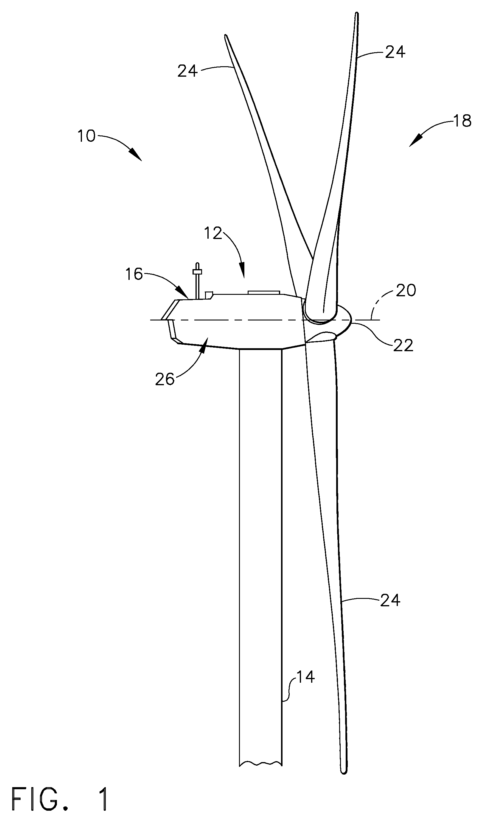
[0020]FIG. 1 is a schematic illustration of an exemplary wind turbine 10. In the exemplary embodiment, wind turbine 10 is a horizontal axis wind turbine. Alternatively, wind turbine 10 may be a vertical axis wind turbine. Wind turbine 10 includes a tower 14, a nacelle 16 coupled to tower 14, and a rotor 18 coupled to nacelle 16 for rotation about an axis of rotation 20. Rotor 18 includes a rotatable hub 22 and a plurality of rotor blades (“blades”) 24 coupled to hub 22. In the exemplary embodiment, rotor 18 includes three blades 24. In an alternative embodiment, rotor 18 may include more or less than three blades 24. General operation, dimensions, and configuration of wind turbine 10, and ...


PUM


Abstract

A mounting system includes a plurality of adjacent railcars including a first railcar that includes spaced first and second wheel assemblies each including at least one wheel pair. The mounting system also includes a first and second frames coupled to the first railcar. The first frame includes a space defined between at least two portions of the first frame and at least one cushion selectively positionable within the first frame space. The second frame includes a space defined between at least two portions of the second frame and at least one cushion selectively positionable within said second frame space. The first and second frames are spaced to facilitate at least one of partially containing and partially supporting the load. The first frame is substantially centered over at least one first wheel assembly wheel pair, and the second frame is substantially centered over at least one second wheel assembly wheel pair.

Description

CROSS REFERENCE TO RELATED APPLICATIONS[0001]This application is a Continuation-In-Part of currently pending U.S. patent application Ser. No. 11 / 343,885 filed Jan. 31, 2006, which is hereby incorporated by reference in its entirety.BACKGROUND OF THE INVENTION[0002]This invention relates generally to transportation methods and systems, and more specifically to methods and systems for transporting wind turbine components by rail.[0003]At least some known wind turbines are disassembled into four types of components such as, but not limited to, rotor blades (“blades”), tower, rotor hubs, and nacelles for transportation. Generally, such wind turbine components are stored in cargo containers and affixed to transport structures such as, but not limited to, railroad cars and / or trucks for transportation to a storage site and / or an assembly site. Such cargo containers facilitate shipping wind turbine components by ship, railroad, and / or truck so that the components may be changed from one tr...

Claims


Application Information

Patent Timeline
IPC IPC(8): F03D7/02
CPCB60P3/40B65D88/121Y02E10/722F03D1/005F03D11/00B65D90/004B61D3/166B61D45/003F03D13/40F03D80/00Y02E10/72
Inventor KOOTSTRA, DIRK-JANBAKER, ERIC ARTHURDAVIS, JOHN P.
Owner GENERAL ELECTRIC CO
Why Eureka
Try Eureka