This presents two major limitations.
First, relying on material properties severely limits the adaptability of the foam.
Foams can be customized to respond optimally to only a very specific range of impact energies, either by changing the density or geometry (thickness) of the foam, but foams are not able to adapt their response to a wide range of impact energies.
A foam that is too soft (not dense enough) for an impact will compress too quickly or “bottom out” and transmit too much force to the impacted body.
A foam that is too hard (too dense) for an impact will not compress enough and will decelerate the impacted body too quickly.
When foam becomes fully compressed under impact, it acts as a
rigid body and loses its ability to absorb energy.
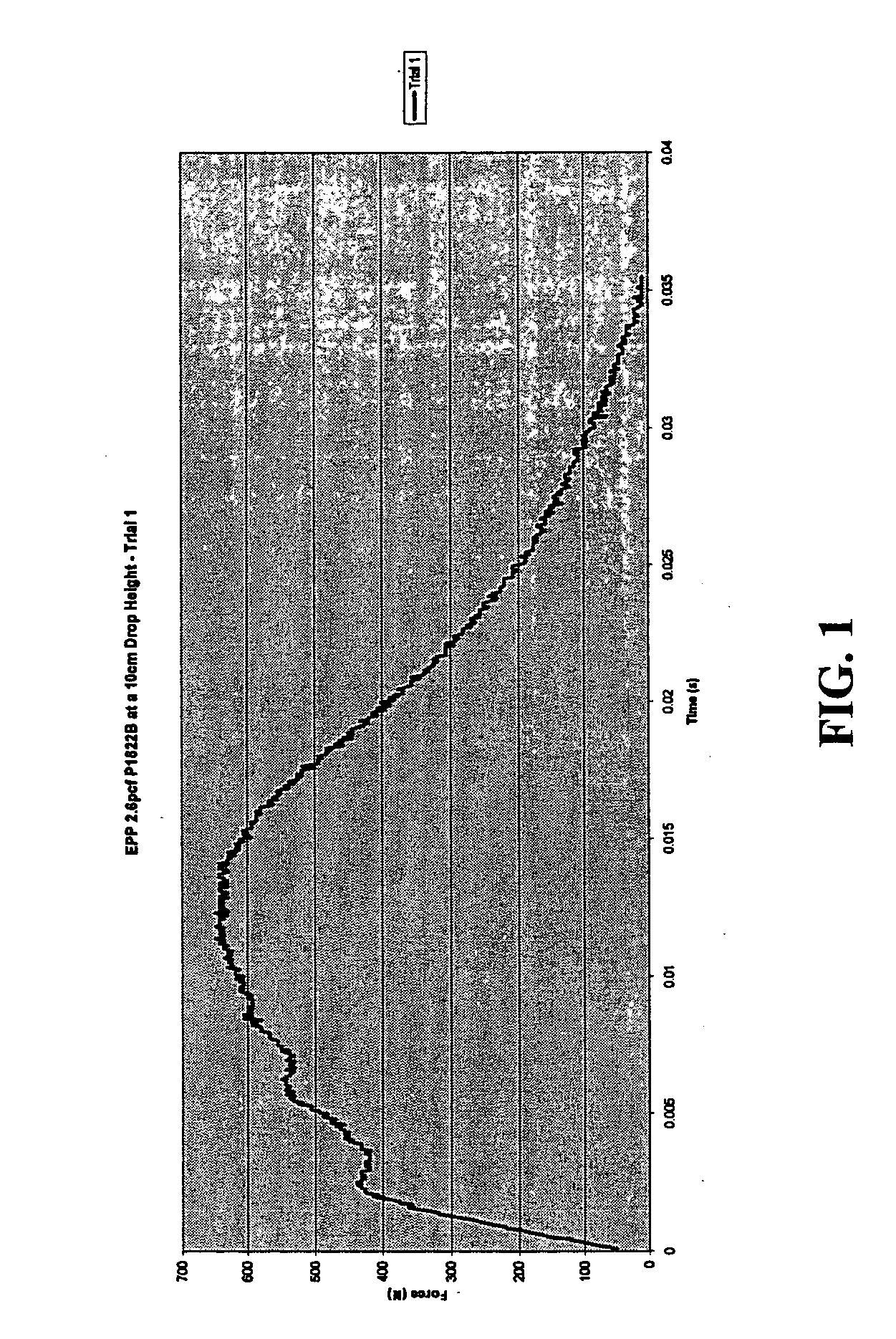
This curve demonstrates that the majority of the deceleration occurs in a brief period of time and distance, thus delivering a
high peak force, which is the most damaging to the impacted body.
In addition, the potential for localized compression of the soft foam decreases the area over which the force may be transmitted, therefore potentially increasing the pressure and damage of the impact.
Due to potentially catastrophic consequences of bottoming out within a small area, soft foams cannot be used in situations that may involve moderate or
high energy impacts.
Conversely, a foam can also be too hard (too dense) for a given impact.
If the foam is too hard, it will present too much resistance in the
early phase of the impact, and will not compress enough (will not “ride-down” enough) to prolong the distance or time of impact.
These dense foams function primarily to spread the
impact area and reduce pressure on the area, but can still lead to high forces.
Another problem with dense foams is the potential for high “rebound,” in which the foam temporarily stores impact energy in compression, then re-delivers it upon rebound.
Thus, dense foams are useful for reducing pressure of impacts, but their ability to significantly reduce peak force is limited.
Even when foams happen to be matched to the impact (which may occur by chance, or by specific
engineering of foams to meet certain very
specific energy level standards), they still have inherent limitations.
One major limitation is the inability of the foam to “ride-down” enough to prolong the distance and time of the impact.
Most foams will ride-down to a maximum of 60-70% of their original height, which limits the distance and time over which the impact occurs, and leads to higher peak forces.
This modification can serve to lower the peak forces, but due to the inherent properties of foam, which cause it to become progressively denser under compression, the curve is still hump- or bell-shaped, limiting the foam's ability to lower peak force.
Further, an
increased thickness of foam may be cosmetically or practically unacceptable for certain applications, and may also increase the bulk and weight of the
energy management system to unacceptable levels.
Given the properties of foam, once it is manufactured, it will have a certain
energy level at which it performs “optimally,” but this performance still leaves great room for improvement, and outside of its optimal range the foam'
s function will be even worse, either being potentially too hard or too soft for a given impact.
Thus, foam lacks an ability to adapt to the potential for impacts of different energy levels.
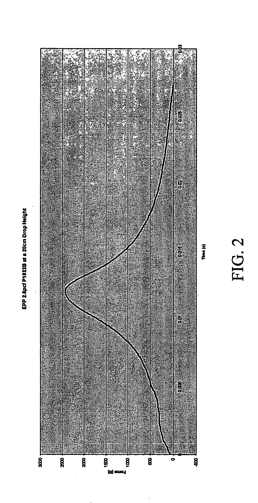
This leads to the use of foams designed simply to perform best at a certain standard, or designed to prevent only the most critical forms of damage, but leaving other forms of damage poorly addressed. FIG. 4 of the drawing includes two Force / Time curves for a given foam generated in response to two different impact energies.
As is apparent from FIG. 4, the foam's performance declines with increased impact energy.
The second major limitation of foam is that all foams will show decline in function after repeated impacts.
Other foams, even though designed to be “multi-impact,” will also decline in function after repeated impacts.
This lack of durability can present practical as well as safety limitations with the use of foams. FIG. 5 of the drawing includes a series of Force / Time curves for successive impacts to a “multi-impact” foam illustrating the decline in the foam's performance with repeated impacts.
(a) limited adaptability;
(d) poor durability.
While we have specifically focused on the limitations of foams, those skilled in the art will appreciate that other mechanisms of
energy management may be employed, and that they may also be subject to the same or similar functional limitations as foam.

