Secondary battery and the fabrication method thereof

Active Publication Date: 2007-08-16
SAMSUNG SDI CO LTD
View PDF5 Cites 9 Cited by
  • Summary
  • Abstract
  • Description
  • Claims
  • Application Information

AI Technical Summary

Benefits of technology

[0018]An object of the invention is to improve the efficiency at which the insulating member is inserted into the inside of the can and rested safely thereon when assembling the insulating member during the fabrication process of the battery.
[0019]Another object of the invention is to suppress the bend of t

Problems solved by technology

First, the injection of the raw material for the conventional insulating member takes place, upon considering the plate as a reference, in the opposite side to the side on which sidewalls are to be formed. Namely, if the sidewalls of the insulating member are extended upwardly in the plate, then the injection of the raw material takes place toward the plate in the lower side of the plate. Thus, “a spot of injecting the raw material” leaves which is defined as a spot formed after the raw material is injected onto the lower surface of the plate. In this spot, a burr which refers to a raised potion formed on the lower surface of the plate after the raw material is injected onto the lower surface of the plate is formed. Accordingly, when an injection-molded insulating member is inserted into the inside of the can by a feeding machine and positioned over the electrode assembly, the insulating member has to be positioned in the target position so that the feeding machine can grasp well the insulating member, however, the lower surface of the plate cannot be maintained flat by the burr formed thereon, and thus the insulating member cannot be positioned in place and can be moved. That is, a problem is arisen that the grasping of the insulating member by the feeding machine becomes difficult due to the scattering of the position of the insulating member, and thus the feeding efficiency is lowered. In order to solve this problem, a burr protruded from the lower surface of the plate has to be removed, which necessitates a separate process, time and cost.
Second, a remaining heat still remains in the insulating

Method used


Image

  • Secondary battery and the fabrication method thereof
  • Secondary battery and the fabrication method thereof
  • Secondary battery and the fabrication method thereof

Examples


Example

[0032]Hereinafter, preferred embodiments of the invention will be described in detail with reference to FIGS. 1 to 6.

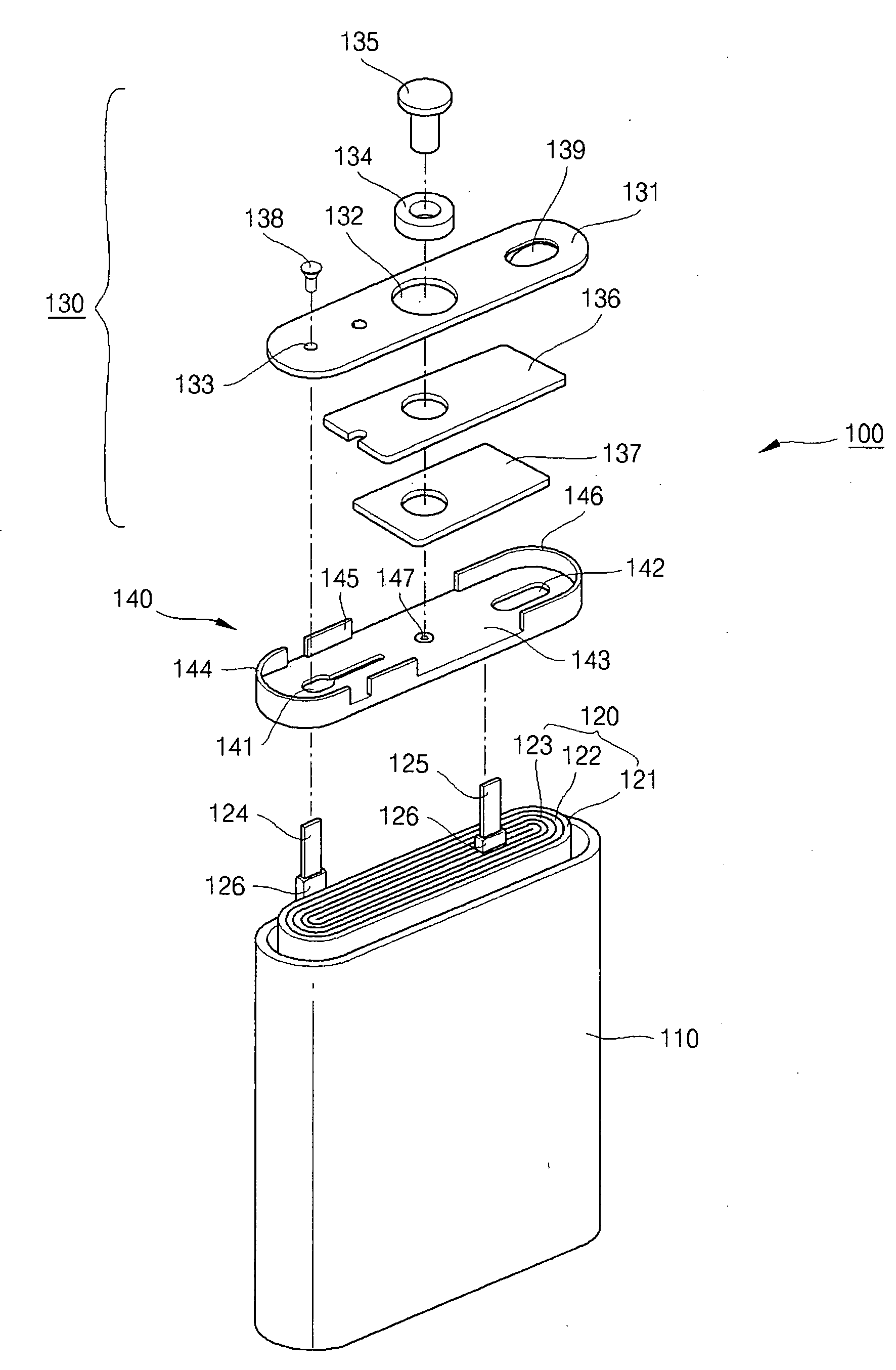
[0033]FIG. 1 is an exploded view illustrating a secondary battery according to a preferred embodiment of the invention.

[0034]A secondary battery 100 comprises an electrode assembly 120 which is accommodated in a container (preferably a can) 110, a cap 130 connected to the top of the opening of the can 110 in a state where the electrode assembly 120 is accommodated in the can 110 and an insulating member 140 interposed between the electrode assembly 120 and the cap 130 for insulating them.

[0035]The electrode assembly 120 is preferably obtained by forming a positive electrode 121 and a negative electrode 123 which have plate shapes so as to increase electric capacity, and interposing a separator 122 between the positive electrode 121 and the negative electrode 123 to be laminated and winding them in the form of a vortex to be formed so-called “Jelly Roll.” The negative ...


PUM

PropertyMeasurementUnit
Angleaaaaaaaaaa
Diameteraaaaaaaaaa
Shapeaaaaaaaaaa

Abstract

A secondary battery, which has no raw material injection spot and a burr on a lower surface of the insulating member. The sidewalls are formed on the opposite side to the side on which bending stress is applied, and the sidewalls act as a structural resistor, which result in preventing the plate from bending. The insulating member inserted into the container has an inversely stepped part to keep the insulating member from escaping from the container. A fabrication method of the secondary battery whereby an insulating member is prepared by inserting a raw material from the side on which the sidewall is to be formed into a mold and solidifying the inserted raw material, the insulating member is positioned over the electrode assembly inserted into a container, and a cap is coupled to an opening of the container with the insulating member positioned over the electrode assembly.

Description

CROSS-REFERENCE TO RELATED APPLICATION AND CLAIM OF PRIORITY[0001]This application claims priority to and the benefit of Korean Patent Application No. 10-2006-0014978, filed on Feb. 16, 2006 the entire content of which is incorporated herein by referenceBACKGROUND[0002]1. Field of the Invention[0003]The invention relates to a secondary battery and the fabrication method thereof, and more particularly, to a secondary battery and the fabrication method thereof which improves the efficiency of feeding of an insulating member to the inside of a container, suppresses the occurrence of the bend of the insulating member, and prevents the insulating member inserted into the inside of the container from escaping from the container.[0004]2. Discussion of Related Art[0005]Generally, secondary batteries are rechargeable and dischargeable batteries which are different from the non-rechargeable primary batteries, and are widely used in high technology electronic devices, such as cellular phone, n...

Claims


Application Information

Patent Timeline
IPC IPC(8): H01M2/08H01M10/04H01M50/183
CPCH01M2/0426H01M2/08Y10T29/49114Y10T29/4911H01M10/058Y02E60/10H01M50/169H01M50/183Y02P70/50F23G5/00B30B9/02B65G2812/0511B09B3/00B09B2101/02B09B3/40
Inventor UH, HWA-LI
Owner SAMSUNG SDI CO LTD
Why Eureka
Try Eureka