Premixed duct burner

a duct burner and premix technology, applied in the direction of incinerator equipment, combustion types, lighting and heating equipment, etc., can solve the problems of high nox emissions, low pressure loss, and limit the amount of turbine exhaust that can interact with supplemental fuel

Inactive Publication Date: 2007-08-16
ALZETA
View PDF7 Cites 3 Cited by
  • Summary
  • Abstract
  • Description
  • Claims
  • Application Information

AI Technical Summary

Problems solved by technology

While this approach may keep pressure losses low in some applications, it limits the amount of turbine exhaust that can interact with supplemental fuel, since all of the added fuel can not immediately mix and burn with all of the TEG.
This higher temperature leads to higher NOx emissions.
Brandon does not teach fully premixing the full exhaust stream with fuel, and therefore makes no attempt to minimize stack oxygen in order to maximize thermal efficiency.
This limits the amount of supplemental heat that can be added by the duct burner.

Method used


Image

  • Premixed duct burner
  • Premixed duct burner

Examples


Embodiment Construction

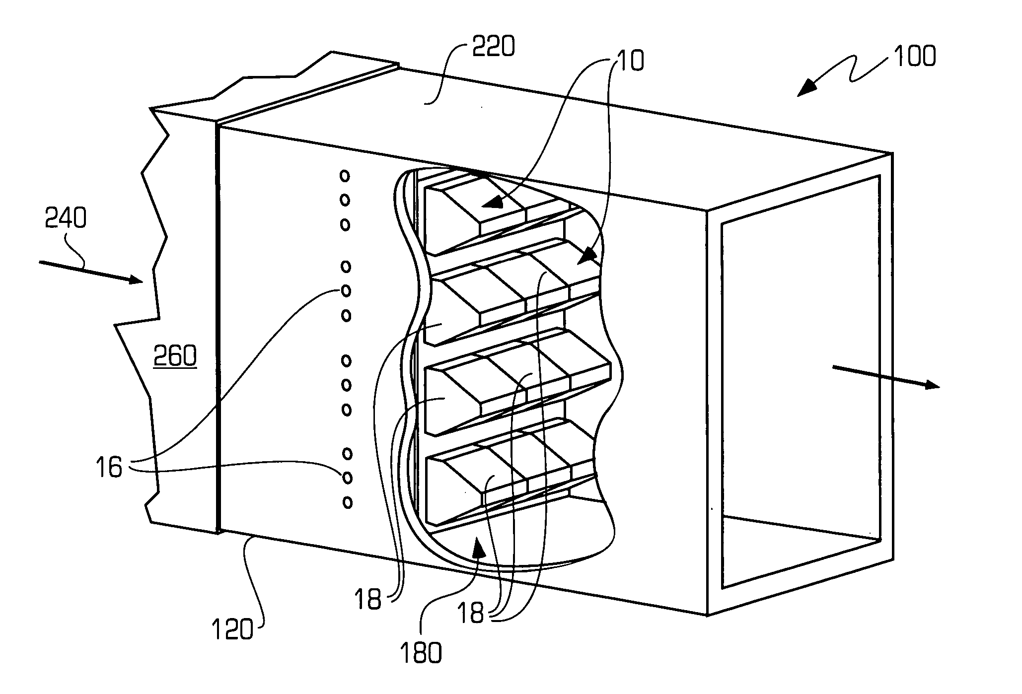
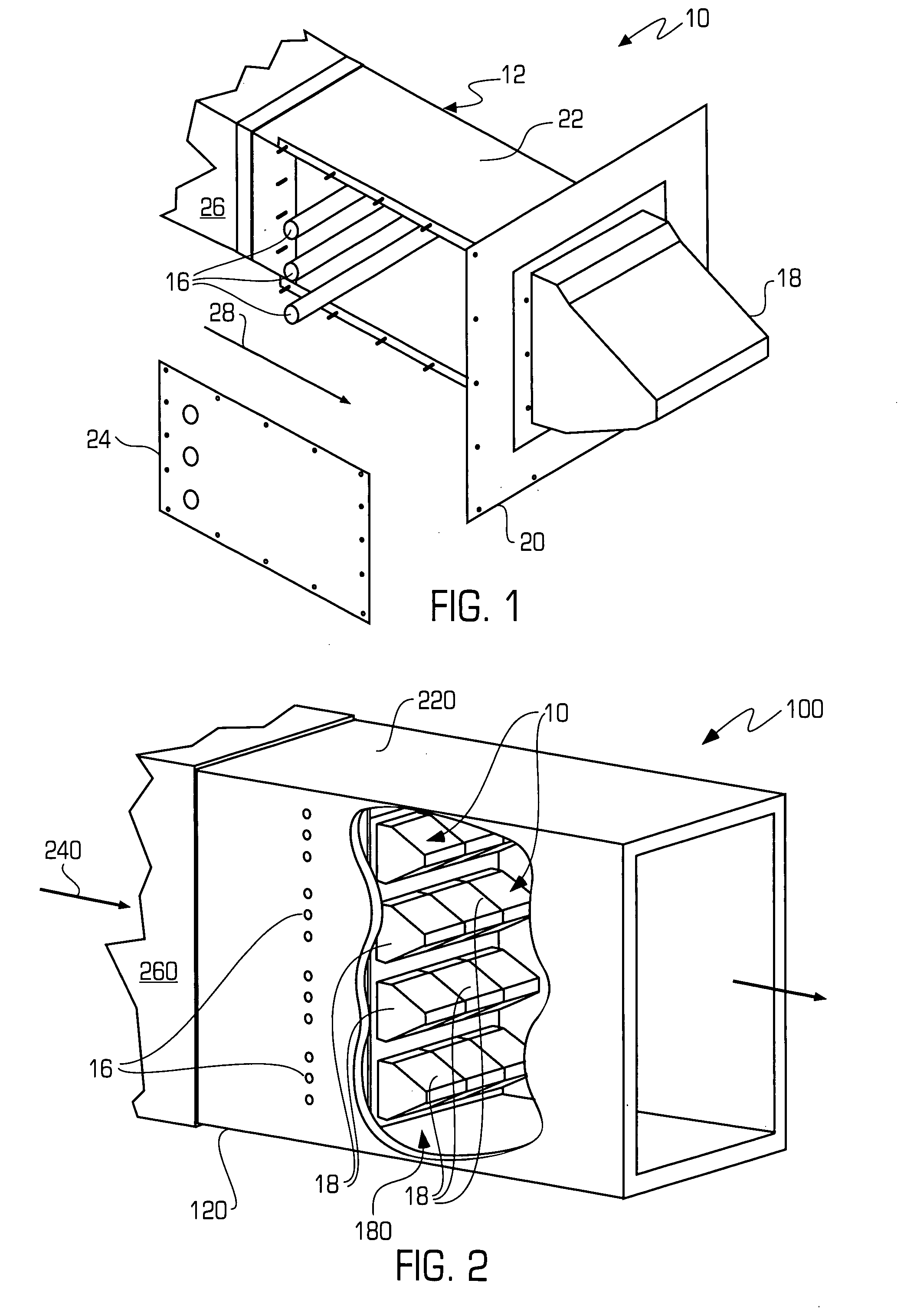
[0013] Embodiments of the present invention will now be described in detail with reference to the drawings, which are provided as illustrative examples of the invention so as to enable those skilled in the art to practice the invention. Where certain elements of the present invention can be partially or fully implemented using known components, only those portions of such known components that are necessary for an understanding of the present invention will be described, and detailed descriptions of other portions of such known components will be omitted so as not to obscure the invention. Embodiments of the present invention are illustrated in the Figures, like numerals being used to refer to like and corresponding parts of various drawings.

[0014]FIG. 1 illustrates one embodiment of a duct burner assembly 10 that is made in accordance with present invention and that is adapted for use in as a supplemental firing burner. Duct burner assembly 10 receives exhaust gas from a power gen...


PUM


Abstract

A fully premixed duct burner is provided that receives exhaust gas from a power generating device, such as a gas turbine or reciprocating engine. The burner may include a burner surface adapted to combust the mixture on or above the surface in blue-flame mode. Substantially all exhaust gas passes through the burner with the exception of some small fraction of exhaust gas that passes through cooling holes or slots. The burner assembly can also include an array of burner modules that receive substantially all of the exhaust gas and fully premixes the exhaust gas with burner fuel prior to combusting the mixture on or above an array of burner surfaces.

Description

FIELD OF THE INVENTION [0001] This invention generally relates to a premixed duct burner and more particularly, to a premixed duct burner for use with gas turbines or reciprocating engines, which has high thermal efficiency and low NOx emissions. BACKGROUND OF THE INVENTION [0002] Power generating devices, such as gas turbines and reciprocating engines, can be implemented to meet the power requirements of industrial and commercial users. In these types of applications, heat recovery is a desirable goal. Heat recovery is commonly achieved through steam generation and may accomplished by passing hot exhaust gasses generated by a device, such as turbine exhaust gas (TEG), through a waste heat boiler or heat recovery steam generator (HRSG). In the simplest systems, there is no supplemental fuel added to the exhaust. These combined power generation and heat recovery systems are known as “combined heat and power” (CHP) systems. [0003] Improved operating flexibility, higher thermal efficie...

Claims


Application Information

Patent Timeline
Patent Type & Authority Applications(United States)
IPC IPC(8): F23D14/62
CPCF23D2203/103F23D2212/103Y02E20/12F23G7/065F23D2212/201
Inventor SULLIVAN, JOHN D.
Owner ALZETA
Why Eureka
Try Eureka