Bandage for wound or incision closure

a technology for wounds and incisions, applied in the field of bandages, can solve the problems of inability to achieve popular acceptance, invasive procedures, and often unsightly scars, and achieve the effects of promoting wound healing, preventing wound inversion, and promoting wound or incision healing

Inactive Publication Date: 2007-08-16
LEBNER MICHAEL
View PDF96 Cites 33 Cited by
  • Summary
  • Abstract
  • Description
  • Claims
  • Application Information

AI Technical Summary

Benefits of technology

[0005] In embodiments of the present invention in which the first and second flat flexible components are thin and extremely flexible, the adhesive protecting film may be selected to provide a degree of stiffness which aids in application of the bandage. Multiple protective films may be provided to protect the adhesive on a single flat flexible component, thereby providing convenient locations to grip the top and protected bottom of the bandage with the fingers during application.
[0011] In preferred embodiments, the first and second pulling elements are removable following application of the bandage to the skin. This feature minimizes the bandage size following application to the patient. This decrease in the overall size of the bandage reduces the chance that a portion of the bandage may be caught, for example, on clothing or a pillow. Such an occurrence could tend to pull the bandage away from the skin thereby causing the wound or incision to open. Minimizing the overall size of the bandage following application also tends to provide for a more comfortable fit.
[0015] An alternative to the interleaved embodiments described above has been termed the wide key-hole design. In this design, two monolithic components are manufactured (e.g., by a die cut process). Each of the two monolithic components comprise a first flat flexible component, elongated connector(s) and a pulling element. The elongated connector(s) of the first monolithic component are all adjacent to one another and centrally located in the assembled and applied bandage. The elongated connectors of the second monolithic component flank those of the first monolithic component lying toward the outside edges of the bandage. This design facilitates manufacture because both monolithic components can be die cut in a conventional manner, then the first monolithic component may be inserted into the relative wide opening between the two sets of elongated connectors in the second monolithic component. When rotated into the same plane, as they are when applied, the monolithic components engage one another resulting in a preferred embodiment of the present invention.
[0016] In another embodiment, the present invention relates to a wound closure device of the type described above, but having only a single elongated connector extending from the first flat flexible component, and a single elongated connector extending from the second flat flexible component. This embodiment is preferred for use in connection with relatively small wounds or incisions. Generally speaking, the width of the flat flexible components of this small wound embodiment is less than about ¾″. This preference for use in connection with relatively small wounds or incisions is based on the fact that the elongated connector extends from its corresponding flat flexible component in an offset manner (i.e., not from the center of the wound edge, but rather to one side of the wound edge). If the flat flexible component were sufficiently wide, say two inches in width, attempts to effect adjustment of the wound edge could be distorted by flexing of the components. On the smaller scales anticipated in connection with this embodiment, the risk of this type of distortion is substantially eliminated.
[0018] A pulling element is provided which extends from each elongated connector on the side of the elongated connector opposite the associated flat flexible component. In preferred embodiments, the pulling element is removable once the device is secured. A perforation in the material from which the device is constructed, along a line substantially perpendicular to the major axis of each elongated connector, is provided for easy removal of the pulling element. Optional features of the type described herein, in connection with other embodiments, are equally applicable to the single elongated connector embodiment.
[0019] When applied to the skin and appropriately tensioned, one edge of the first flat flexible component and one edge of the second flat flexible component are positioned nearest to and substantially parallel to the wound or incision. These edges will be referred to herein as the wound edges. In preferred embodiments of the present invention, the wound edges are adapted to evert (or raise) skin edges to promote wound healing. It is known in the art that everting, raising or mounding of the skin edges at the wound or incision site prevents wound inversion. One way in which this may be accomplished is to provide a bend at the wound edge. The bend may be angled or arcuate. The adhesive on the lower portion of the flat flexible components is also applied to the portion of the wound edge. When attached to the skin this eversion edge tends to lift the edges of the skin at the point of closure contact, thereby promoting wound or incision healing.

Problems solved by technology

The use of sutures or staples is an invasive technique which can be painful and frequently the use of an anesthetic is required.
These processes often leave unsightly scars, both from the insertion holes and from varying tensions applied to the wound or surgical incision between the suturing points and intervening spaces.
Moreover, these methods necessitate follow-up visits to a hospital or doctor's office for removal.
Although other compositions and methods for closing wounds or incisions are known in the art, these have not gained popular acceptance due to limitations in their design.

Method used


Image

  • Bandage for wound or incision closure
  • Bandage for wound or incision closure
  • Bandage for wound or incision closure

Examples


Embodiment Construction

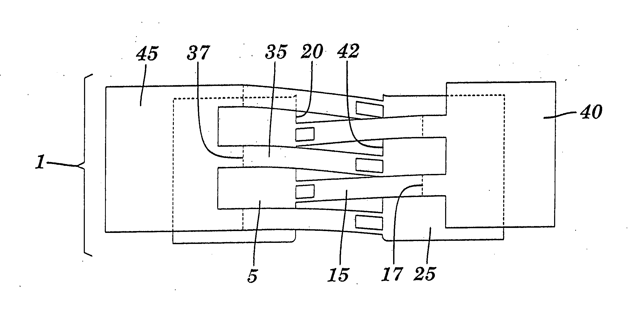
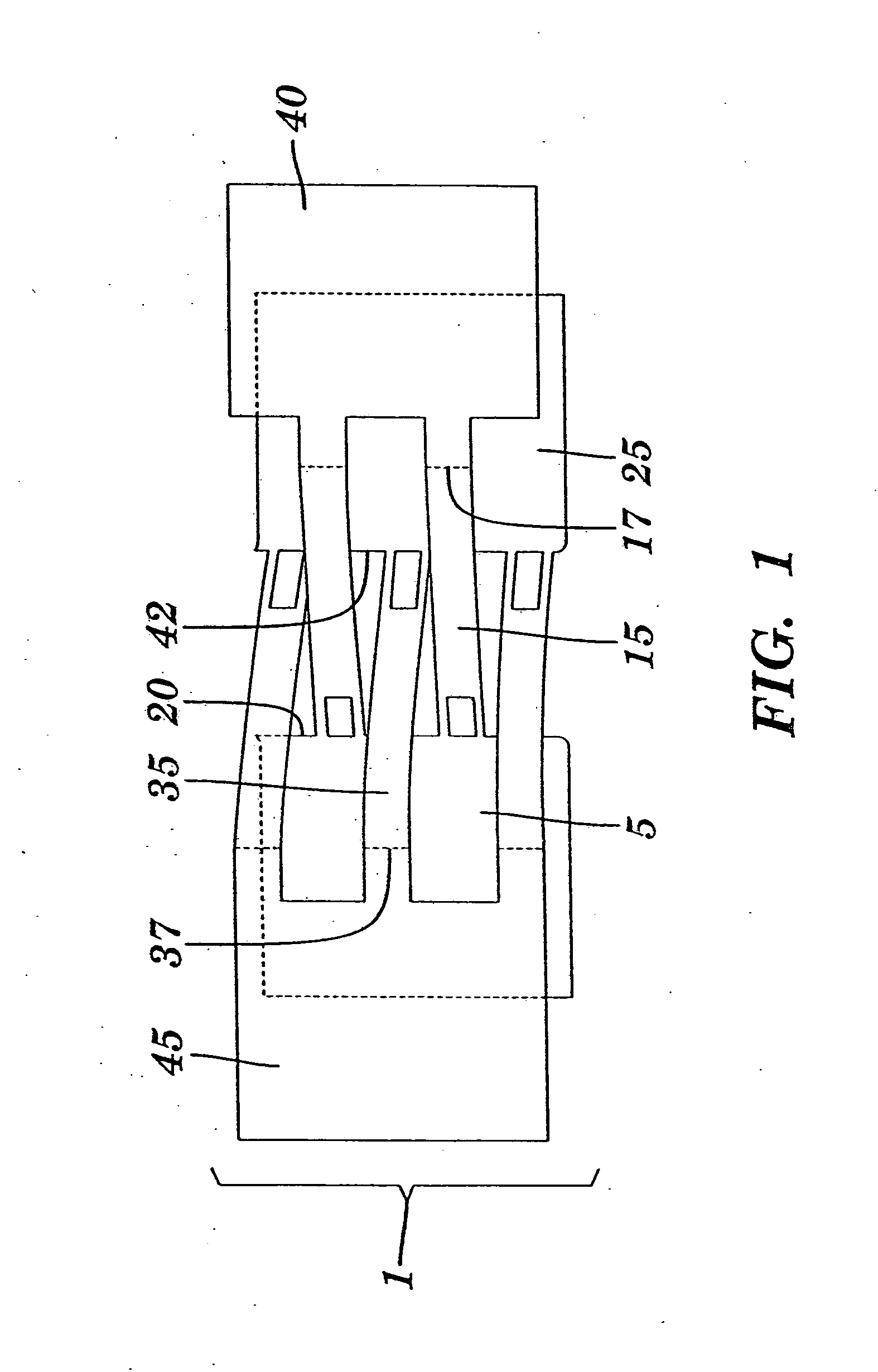
[0036] A bandage of the present invention in a non-tensioned state is depicted in FIG. 1. Bandage (1) includes a first flat flexible component (5) and a second flat flexible component (25). Each of these components has an upper surface to which lead lines 5 and 25 are directed, and lower surfaces which are not visible in the drawing. The lower surfaces are coated with adhesive to facilitate attachment to the skin. A plurality of first elongated connectors (15) extend from the wound edge (20) of the first flat flexible component (5) in a first direction, and a plurality of second elongated connectors (35) extend from the wound edge (42) of the second flat flexible component in a second direction which is generally opposite to the first direction. A first pulling element (40) is joined to the first elongated connectors (15) and adapted for lateral translation of the first flat flexible component (5) toward a wound or incision. Similarly, a second pulling element (45) is joined to the ...


PUM


Abstract

Disclosed is a bandage for closing a wound or incision, and methods for the use of same. The bandage comprises a first flat flexible component having adhesive on a lower surface and one or more first elongated connectors extending in an offset manner from one edge thereof in a first direction. The bandage further comprises a second flat flexible component having adhesive on a lower surface and one or more second elongated connectors extending in an offset manner from one edge thereof in a second direction generally opposite to the first direction. Pulling elements are joined to the first and second elongated connectors. Means are provided for attaching the first elongated connectors to the second flat flexible component and the second elongated connectors to the first flat flexible component.

Description

BACKGROUND OF THE INVENTION [0001] Compositions and methods for wound or incision closure are known in the art. The use of sutures or staples to close a wound or incision represents the most common of these prior art techniques. The use of sutures or staples is an invasive technique which can be painful and frequently the use of an anesthetic is required. These processes often leave unsightly scars, both from the insertion holes and from varying tensions applied to the wound or surgical incision between the suturing points and intervening spaces. Moreover, these methods necessitate follow-up visits to a hospital or doctor's office for removal. [0002] Although other compositions and methods for closing wounds or incisions are known in the art, these have not gained popular acceptance due to limitations in their design. There is a clear need for non-, or less invasive method for wound or incision closure which is practical and easy to use. SUMMARY OF THE INVENTION [0003] The present i...

Claims


Application Information

Patent Timeline
Patent Type & Authority Applications(United States)
IPC IPC(8): A61F15/00A61F13/00A61B17/08A61B17/04A61B19/00
CPCA61B17/0466A61B2019/464A61B2017/086A61B17/085A61B2090/064
Inventor LEBNER, MICHAEL
Owner LEBNER MICHAEL
Why Eureka
Try Eureka