
Apparatus and method for door and window side flashing

a technology for side flashing and windows, applied in the field of door or window side flashing system, can solve the problems of difficult opening and closing of windows or doors, unsatisfactory friction, etc., and achieve the effects of convenient installation, convenient vertical folding, and convenient installation

Inactive Publication Date: 2007-08-23
TEODOROVICH MISHKO
View PDF19 Cites 28 Cited by
  • Summary
  • Abstract
  • Description
  • Claims
  • Application Information

AI Technical Summary

Benefits of technology

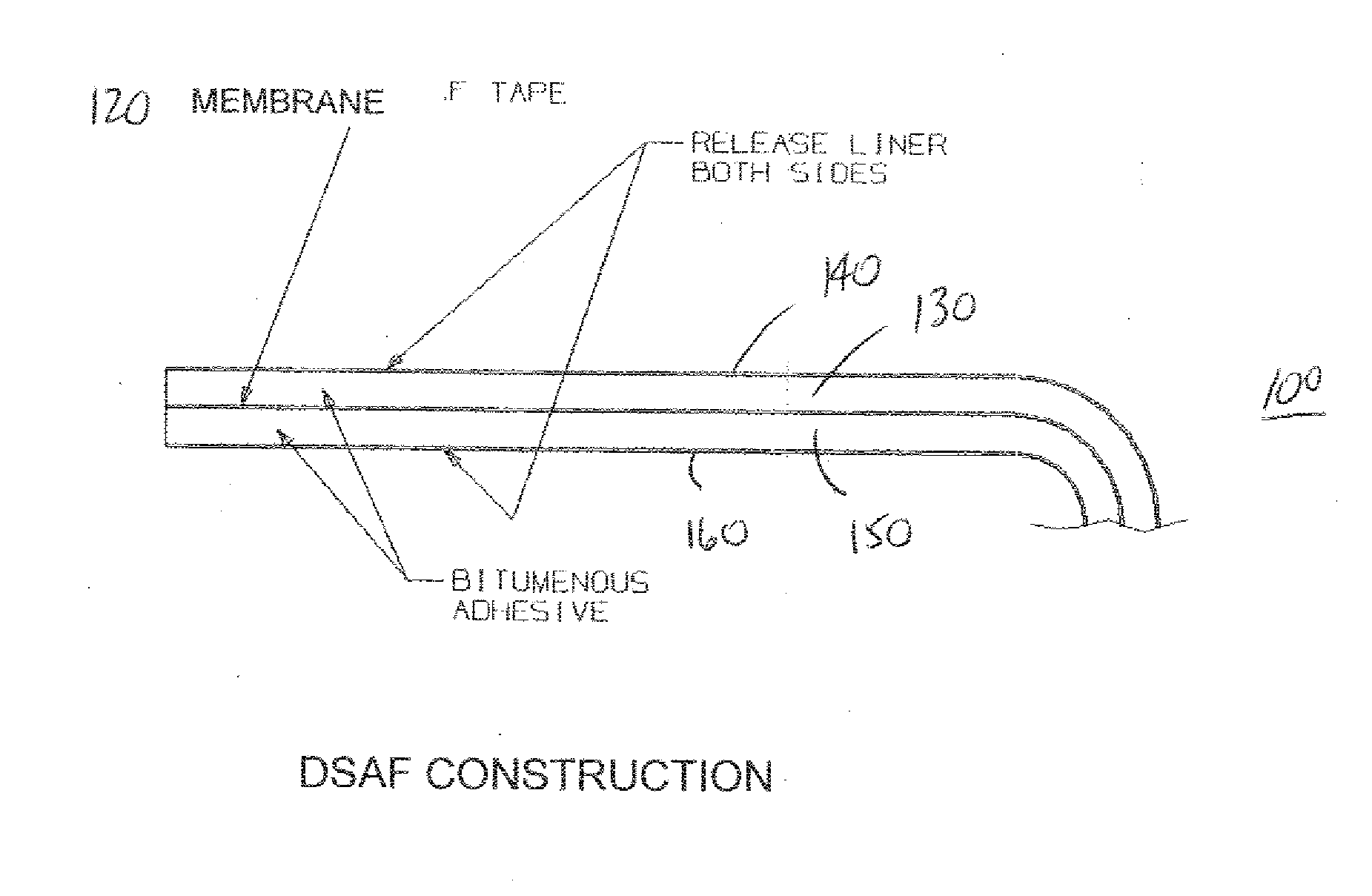
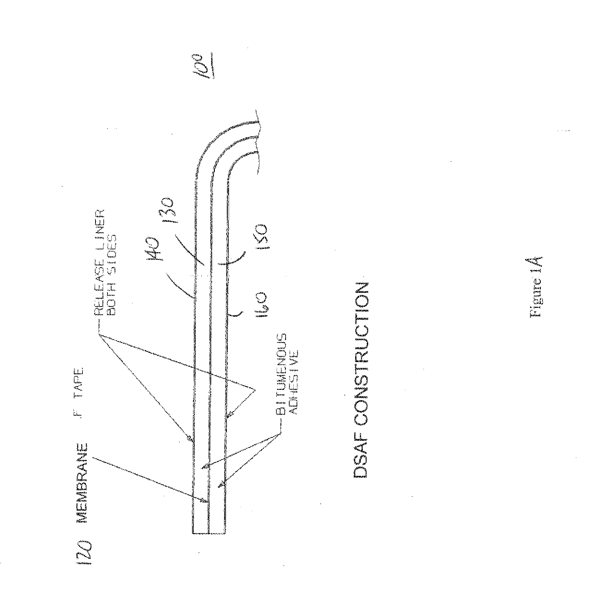
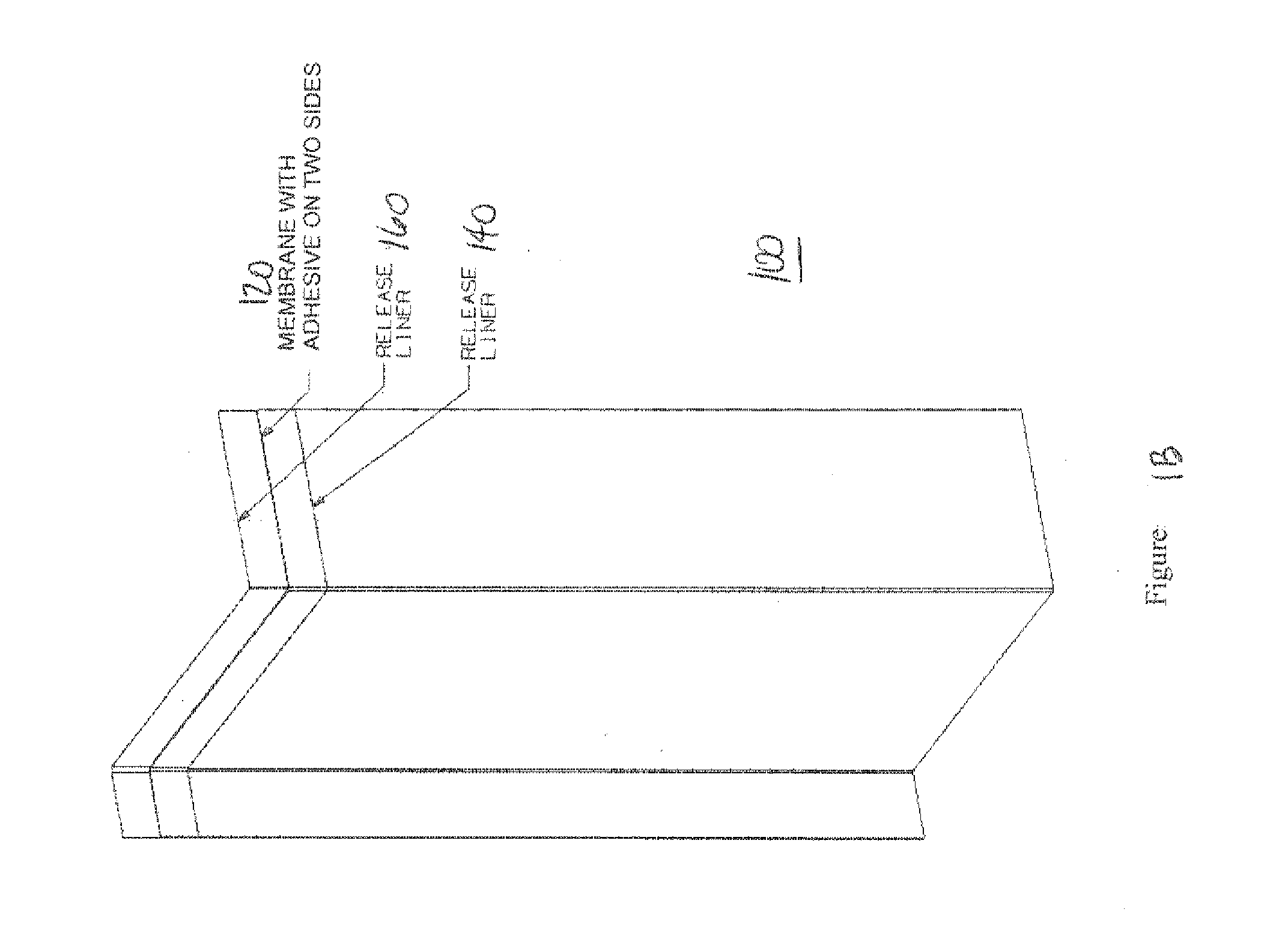
[0014] The current invention is for a window and door side flashing system and method, which used in combination with other devices and methods prevents water intrusion and accumulation around windows and doors. The SureSill SideFlash™ is designed to provide a barrier to water intrusion from the sides of windows or doors, and to discharge water to the exterior of the building.
[0017] The strips make installation easier. The release liner can be configured in various means to facilitate the installation. For example, FIG. 2A has the release liner shown with slits; and FIG. 2B shows perforations, which may facilitate making the vertical folds in the self adhesive flashing. FIG. 2C shows the release liner overlapping to allow easier edge access for removal.

Problems solved by technology

One disadvantage to an expandable foam is that the expansion can cause the jamb to bulge and cause undesirable friction between the door or window and the jamb.
This friction makes it difficult to open and close the window or door.

Method used


Image

  • Apparatus and method for door and window side flashing
  • Apparatus and method for door and window side flashing
  • Apparatus and method for door and window side flashing

Examples


first embodiment

[0059]FIG. 3A is a top cross sectional view of a window or door jamb 186 with a SideFlash™ flashing treatment. In this embodiment, the DSAF 100 is applied between the wall stud 300 and the jamb 186.

[0060] The DSAF includes an exterior section 331 with an inside surface 332 and an outside surface 333 which faces away from the exterior sheeting 320; a jamb section 334 with an inside surface 335 facing the wall stud 300 and an outside surface 336 facing the jamb 186; and an interior section 337 with an inside surface 338 facing toward the jamb and an outside surface 339 facing toward the interior trim (not shown) and away from the drywall 310. In this embodiment, the DSAF is bent to provide a seal 360 between the jamb 186 and the wall frame 300.

[0061] In this embodiment, an adhesive 340 (not shown) may be provided or applied between the flashing and several surfaces including surface 338 between the an interior section 337 and the door or window jamb; surface 363 between the door or w...

second embodiment

[0063]FIG. 3B is a top cross sectional view of a window or doorjamb with a SideFlash™ flashing treatment. In this embodiment, a portion of the DSAF 370 is doubled back over the door or window flange 188. In FIG. 3B, DSAF is turned back and adhered over the window / door nailing flange, over the fasteners, and over the joint 381 where the flange meets the jamb, providing additional seal against moisture intrusion from several locations. The flashing may also be bent to form section 380 and adhered to the door or window jamb 186 at surface 382.

third embodiment

[0064]FIG. 3C is a top cross sectional view of a window or door jamb with a SideFlash™ flashing treatment. In this embodiment, a first portion 333b is adhered to a portion of the brick mold 390, and a second portion 333a is not adhered to another surface.


PUM


Abstract

A window and door side flashing is installed with a double self adhesive flashing. The flashing may be provided as a tape or sheets, with adhesive pre-applied to both sides of a substrate. Protective liners may be removed in strips from either side of the flashing in order to expose a desired width of adhesive for attachment to portions of door or window jamb, framing, brick mold, or exterior sheeting. Other areas of the flashing remain covered to permit easier handling and installation. After application, the flashing provides a continuous barrier to water intrusion. In other embodiments, an extruded plastic flashing is provided. The flashing may have flexible fins to seal against water intrusion.

Description

RELATED APPLICATIONS [0001] This application claims the benefit of U.S. Provisional patent application No. 60 / 757,684 filed Jan. 10, 2006 by applicant.FIELD OF INVENTION [0002] This invention relates to a door or window side flashing system, devices, and methods to direct moisture away from the inside of a structure; for installation of roofing membrane or underlayment; and for installation of weather resistive barrier on the exterior of the building. BACKGROUND [0003] It is desirable to provide window and door side flashing to prevent water intrusion and to promote drainage. It is desirable that the apparatus and method can be used for construction in all price ranges of housing, and for any door or window height or depth. [0004] When installing a door or a window, it is desirable to seal against the water intrusion into the wall cavity and into the building. The seal between the building and the window or door nailing flange or brick mold is frequently accomplished by adhesive cau...

Claims


Application Information

Patent Timeline
Patent Type & Authority Applications(United States)
IPC IPC(8): E04D13/14
CPCE04D1/36E06B2001/628E06B1/62E04D12/002
Inventor TEODOROVICH, MISHKO
Owner TEODOROVICH MISHKO
Learn More