Concentrating solar panel and related systems and methods

a technology of solar panels and concentrating modules, applied in the safety of solar heat collectors, lighting and heating equipment, light radiation electric generators, etc., can solve the problems of limiting the market penetration of photovoltaic solar power, affecting the overall daily exposure of users to sunlight, and requiring many years for users' electric bill savings to pay back the cost of solar panels. achieve the effect of increasing the overall exposure to sunlight, and increasing the overall daily exposure of users

Inactive Publication Date: 2007-08-23
SOLIANT ENERGY INC
View PDF99 Cites 122 Cited by
  • Summary
  • Abstract
  • Description
  • Claims
  • Application Information

AI Technical Summary

Benefits of technology

[0014] Preferably, photovoltaic concentrator modules of the present invention are constructed to articulate in only one axis to point at and track the sun. Advantageously such an arrangement can help eliminate expensive large round bearing rings associated with a second axis.
[0015] Also, photovoltaic concentrator modules of the present invention preferably articulate individually with respect to a fixed support structure. Doing so can help maintain a low profile for a solar panel which can in turn help make the panel more suitable for rooftop installation.
[0016] Another feature of the present invention includes unique troughs of linear, photovoltaic concentrator modules. Advantageously, such troughs can function simultaneously as a concentrating optical element, a structural element, and a cooling element. As yet another advantage, such a trough can help eliminate, if desired, the need for separate components to perform these functions.
[0018] For example, a concentrator module according to the present invention can be compact in height thereby allowing modules to be packed together into a compact solar panel while still being able to articulate a module in concert with adjacent modules without collision among the articulating modules. Or, rather than packing the individual concentrators right next to each other, an amount of space can be provided between the individual concentrators so that the concentrators can operate without shading each other through a larger portion of the day and / or of the year. This innovation would allow the panel to lie flat on the roof rather than having to articulate the entire panel to point at the sun and / or would allow a more cost-effective use of the individual concentrators by increasing their overall daily exposure to sunlight.
[0020] Yet another advantage is that a system according to the present invention can be mounted in its target installation (e.g., on residential or commercial rooftops, covered parking structures and walkways, and the like (e.g., to a support post driven deep into the ground)) using whatever technique the installer traditionally uses, whether a non-penetrating flat rooftop mount like the Powerlight® Powerguard® system, an anchored mount for a residential rooftop, a latitude-tilt mount, or even a ground mount or mounting on a single-axis tracker. The installer and end user can choose whatever mounting approach makes the most sense for them.
[0021] Additional advantages include one or more of the following: 1) higher efficiencies and / or lower costs (e.g., produce electricity economically and at a cost that can be much lower than many traditional solar panels), 2) the ability to penetrate markets currently dominated by traditional flat solar panels, and / or 3) increased acceleration of deployment of such concentrating solar systems into the market. In preferred embodiments, installers of traditional flat solar panels can use existing mounting hardware and installation techniques to install a concentrating solar system according to the present invention. Even sales and marketing techniques for traditional flat solar panels can be utilized for a concentrating solar panel according to the present invention.

Problems solved by technology

Traditional solar panels tend to be costly and typically take many years for the user's electric bill savings to pay back the cost of the panels.
This has contributed to limiting the market penetration of photovoltaic solar power.

Method used


Image

  • Concentrating solar panel and related systems and methods
  • Concentrating solar panel and related systems and methods
  • Concentrating solar panel and related systems and methods

Examples


Embodiment Construction

[0048] The embodiments of the present invention described below are not intended to be exhaustive or to limit the invention to the precise forms disclosed in the following detailed description. Rather a purpose of the embodiments chosen and described is so that the appreciation and understanding by others skilled in the art of the principles and practices of the present invention can be facilitated.

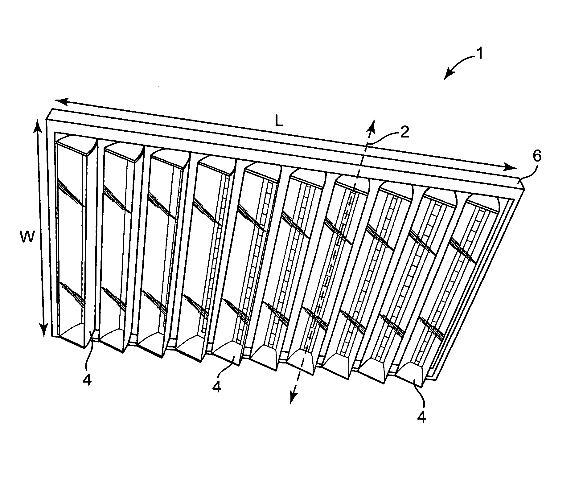
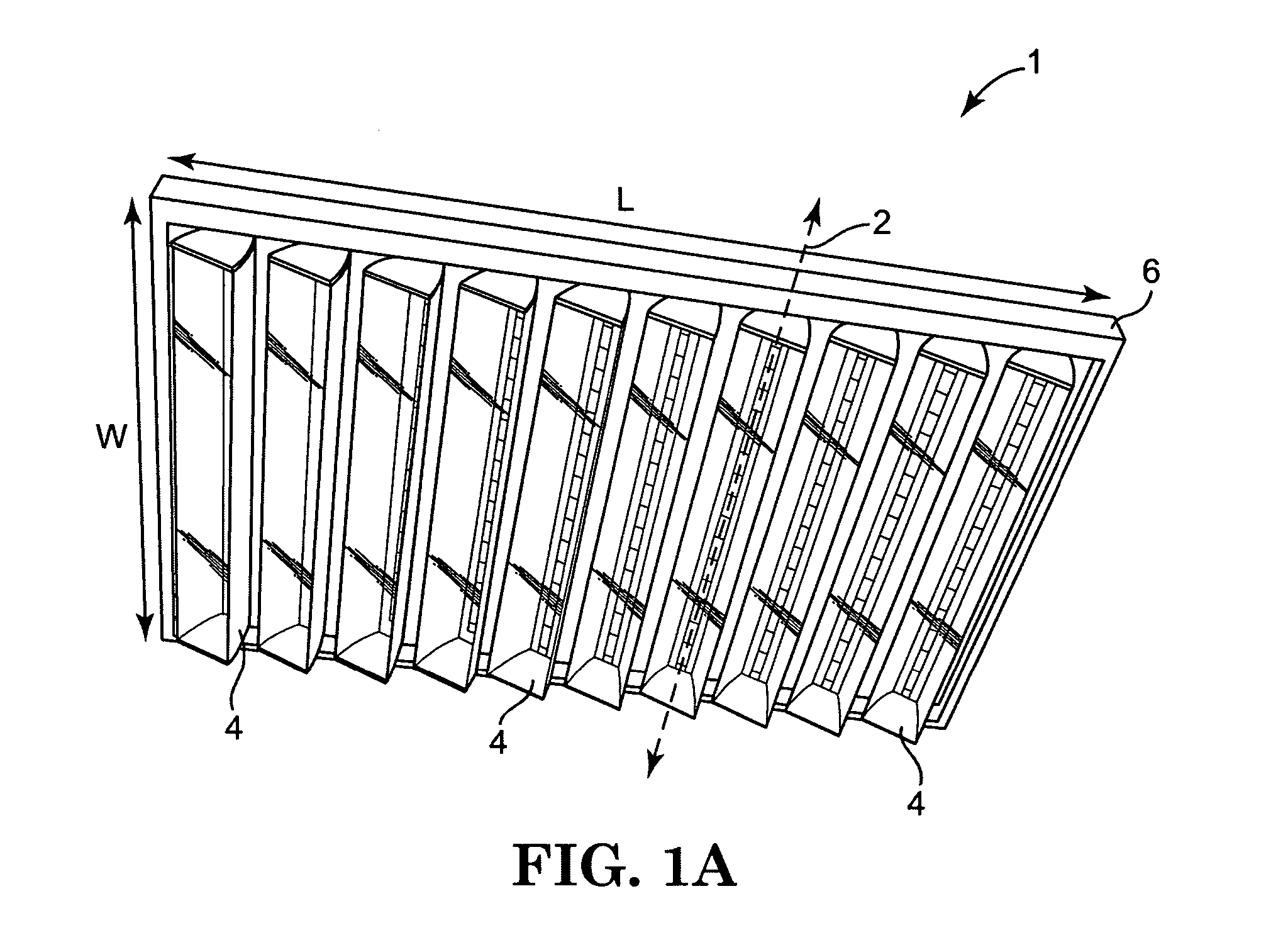
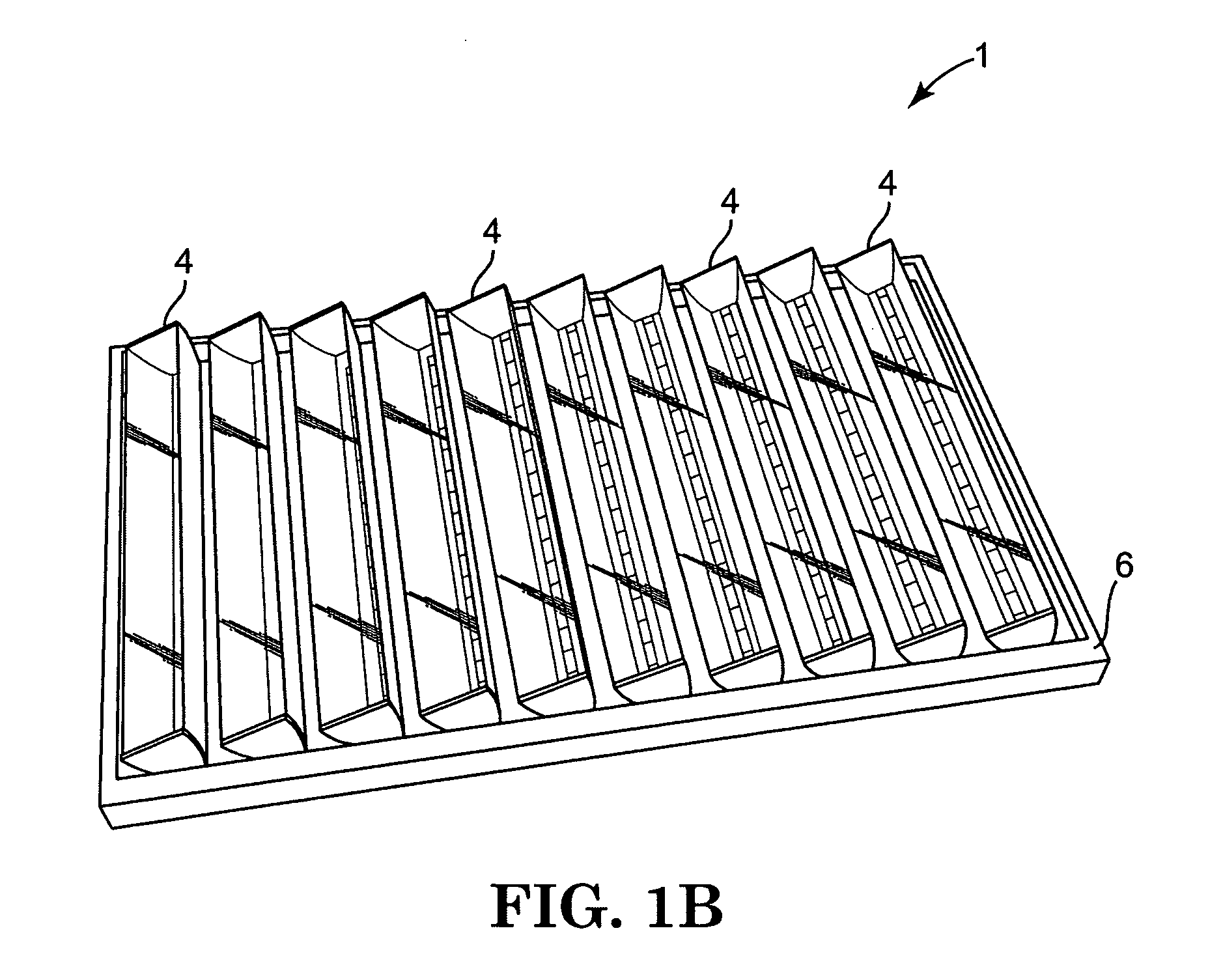
[0049]FIGS. 1A-6B illustrate at least part of a preferred photovoltaic power system 1 according to the present invention. Photovoltaic power system 1 includes a plurality of moveable, linear concentrator modules 4 mounted in a frame 6, electronic control unit 22, circuit 28, and mechanical linkages (not shown) that allow movement of the modules 4 to track the sun. As shown, each concentrator module 4 preferably includes a reflective trough 8, a cover 10 incorporating a lens 14 as a portion of the cover 10, a receiver 12, end caps 20, and sensor 24. The modules 4 incorporate a hybrid opti...


PUM


Abstract

The present invention relates to photovoltaic concentrating modules and related concentrating solar systems and methods. In particular, the present invention relates to concentrating modules, especially modules having a convenient size and market acceptance of traditional flat photovoltaic solar panels.

Description

PRIORITY CLAIM [0001] The present nonprovisional patent Application claims priority under 35 U.S.C. §119(e) from U.S. Provisional Patent Application having Ser. No. 60 / 759,778, filed on Jan. 17, 2006, by Braden E. Hines and titled CONCENTRATING SOLAR PANEL AND RELATED SYSTEMS AND METHODS, wherein the entirety of said provisional patent application is incorporated herein by reference.FIELD OF THE INVENTION [0002] The present invention relates to photovoltaic concentrating modules and related concentrating solar systems and methods. In particular, the present invention relates to concentrating modules and systems having a convenient size and market acceptance of traditional flat photovoltaic solar panels. BACKGROUND OF THE INVENTION [0003] Traditional solar panels tend to be costly and typically take many years for the user's electric bill savings to pay back the cost of the panels. This has contributed to limiting the market penetration of photovoltaic solar power. It is desirable, t...

Claims


Application Information

Patent Timeline
Patent Type & Authority Applications(United States)
IPC IPC(8): H02N6/00F24S23/30F24S23/71F24S50/20
CPCF24J2/06H01L31/0547F24J2/10F24J2/38F24J2/4612F24J2/54F24J2/541F24J2002/0084F24J2002/108F24J2002/5468Y02B10/12Y02B10/20Y02E10/44Y02E10/47Y02E10/52H02S20/00F24J2/08H02S20/30H02S40/22F24S23/00F24S2020/16F24S50/20F24S23/70F24S30/425F24S2023/872F24S40/40F24S30/40F24S23/30F24S2030/136Y02B10/10H02S20/32H01L31/042
Inventor HINES, BRADEN E.JOHNSON, RICHARD L. JR.IRWIN, PHILIP C.
Owner SOLIANT ENERGY INC
Why Eureka
Try Eureka