Apparatus for handling and racking pipes

Active Publication Date: 2007-08-23
WEATHERFORD CANADA
View PDF22 Cites 41 Cited by
  • Summary
  • Abstract
  • Description
  • Claims
  • Application Information

AI Technical Summary

Benefits of technology

[0009] The apparatus according to the present invention is mounted near the center of the pipe path. The support and spanning components may thus be smaller than in the prior art due to the reduction of reach required. The apparatus stabilizes and supports a pipe stand being transported between the well bore axis in a derrick and a pipe rack such that unwanted movement of the pipe stand, which affects the rate of racking, may be reduced,

Problems solved by technology

While the prior art provides devices for handling pipe stands, they do not provide the solution according to the present invention to address the conventional inefficiencies and the instability associated with manipulating and transporting pipe stands that may exceed thirty feet in length and several tonnes in weight.
In the Krueger patent, a clamp engages only an upper portion of the pipe to effect vertical and rotational movement, leaving the mid-portion and lower portion of the pipe vulnerable to undesired swaying movement whic

Method used


Image

  • Apparatus for handling and racking pipes
  • Apparatus for handling and racking pipes
  • Apparatus for handling and racking pipes

Examples


Embodiment Construction

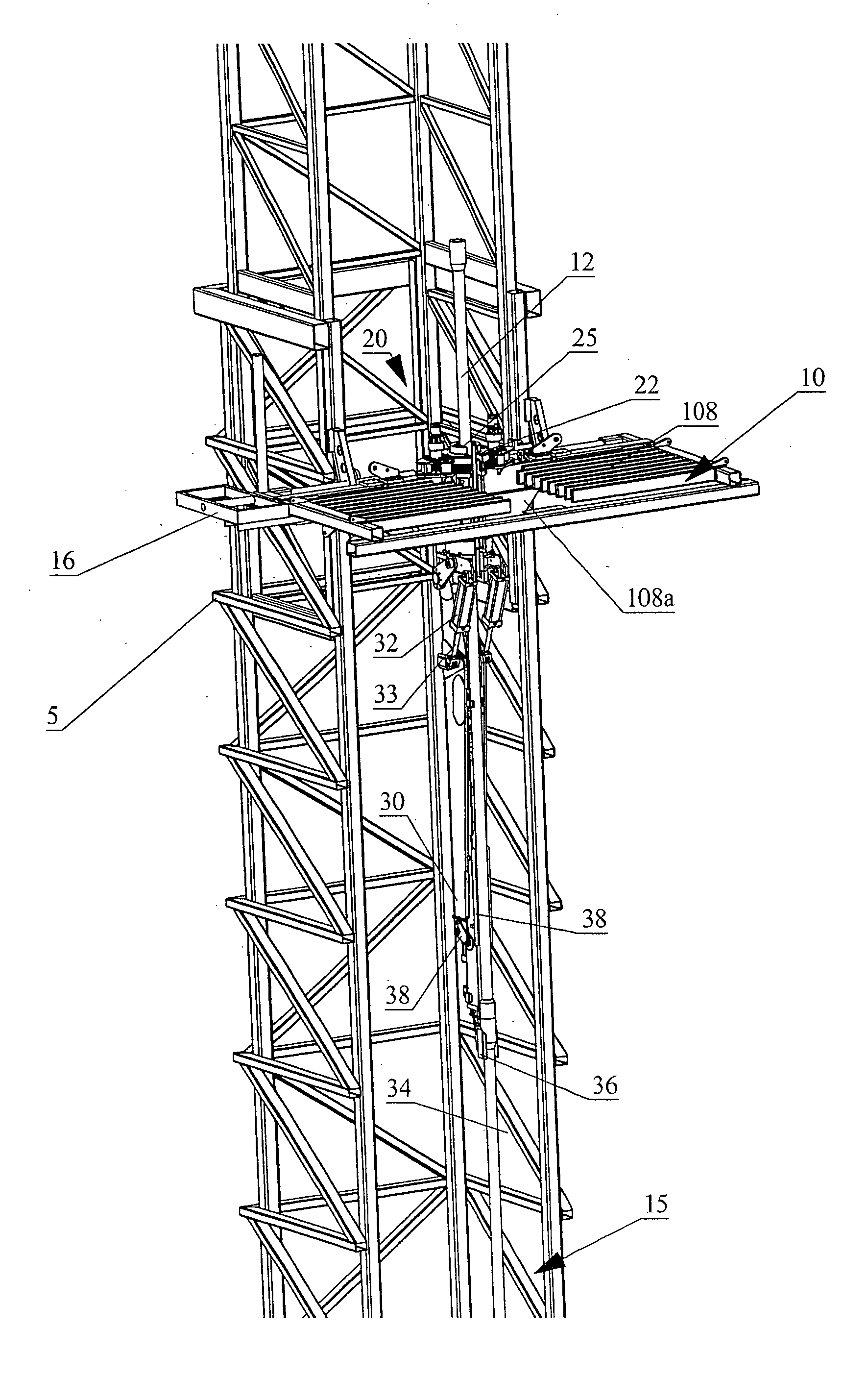
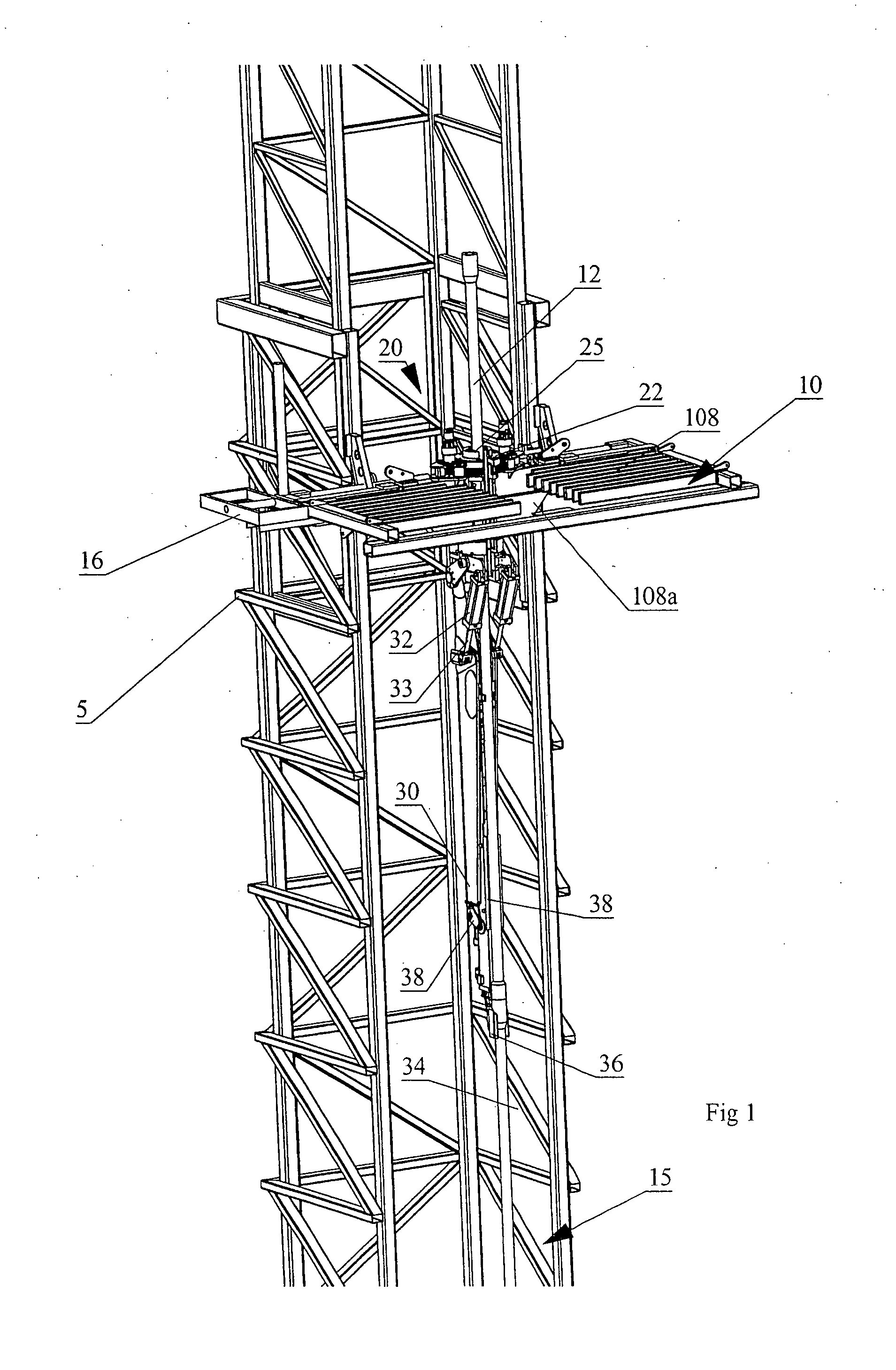
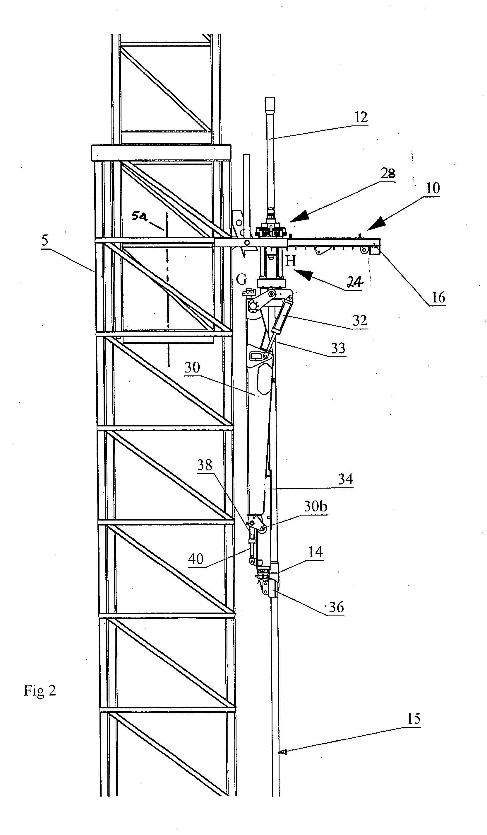
[0040] With reference to the Figures wherein similar characters of reference denote corresponding parts in each view, the apparatus for handling pipes according to the present invention is mounted on a derrick 5 having a well bore axis or well center 5a. The apparatus includes a pipe racking assembly 10 and a rotatable gate assembly 20 mounted thereto. In an embodiment of the present invention, the apparatus for handling pipes is configured to handle and rack a plurality of pipe stands 12 which are detachably coupled together to form a drill string 15. Pipe stands 12 are formed by coupling a plurality of pipe joints together. The ends of each pipe joint are flared such that at the point of coupling between pipe joints and pipe stands 12, an annular flange known in the art as a tool joint 14 is formed.

[0041] In an embodiment of the invention, pipe racking assembly 10 includes a generally planar and rectangular frame which is horizontally disposed when mounted on derrick 5. Pipe rack...


PUM


Abstract

An apparatus and method for handling pipes in a derrick and racking the pipes on a pipe racking assembly mounted on the derrick. The apparatus includes a rotatable gate assembly rotatably mounted on the pipe racking assembly. The rotatable gate assembly includes a collar rotatably mounted to a first end of a rotatable pipe support. A pipe manipulator arm is pivotably mounted on a second end of the rotatable gate assembly. The collar defines a gate for securing an upper portion of the pipe stand. A pipe mount is mounted to a distal end of the arm for holding the pipe stand for transport between the derrick and the gate, and between the gate and the pipe rack. After the arm secures the pipe stand into the gate from the derrick, a drive mechanism rotates the rotatable gate assembly to a rack facing position from the derrick facing position such that the arm may transport the pipe between the gate and the pipe rack.

Description

CROSS REFERENCE TO RELATED APPLICATION [0001] This is a Continuation-in-Part Patent Application of U.S. patent application Ser. No. 10 / 997,930 filed Nov. 29, 2004.FIELD OF THE INVENTION [0002] This invention relates to the field of equipment used in the drilling industry, and more particularly, it relates to an apparatus for manipulating and racking pipes in a drilling derrick. BACKGROUND OF THE INVENTION [0003] In drilling operations, the derrick is the structure designed to support and manipulate the drill string in and out of the well bore. The drill string is a series of drill pipe segments detachably connected together. Typically, the drill pipe segments are coupled together to form a pipe stand of a predetermined or standard length and the pipe stands are then coupled together to form the drill string. [0004] A drill collar and a drill bit are attached to a drill end of the drill string. The drill collar is a heavier pipe having a larger diameter which fits around the drill pi...

Claims


Application Information

Patent Timeline
IPC IPC(8): E21B19/00
CPCE21B19/20E21B15/00E21B19/14
Inventor WRIGHT, MONTE NEILSTROSHEIN, WILLIAM JOHNRICHARD, DAVID LOUISBANISTER, ANDREW SCOTT
Owner WEATHERFORD CANADA
Why Eureka
Try Eureka