Planar multi-electrode array sensor for localized electrochemical corrosion detection

a multi-electrode array, localized technology, applied in the direction of liquid/fluent solid measurement, material electrochemical variables, instruments, etc., can solve the problem of local corrosion of anodic sites

Active Publication Date: 2007-08-23
SOUTHWEST RES INST
View PDF19 Cites 32 Cited by
  • Summary
  • Abstract
  • Description
  • Claims
  • Application Information

AI Technical Summary

Problems solved by technology

When these sites are far apart, the anodic sites corrode locally.

Method used


Image

  • Planar multi-electrode array sensor for localized electrochemical corrosion detection
  • Planar multi-electrode array sensor for localized electrochemical corrosion detection
  • Planar multi-electrode array sensor for localized electrochemical corrosion detection

Examples


Embodiment Construction

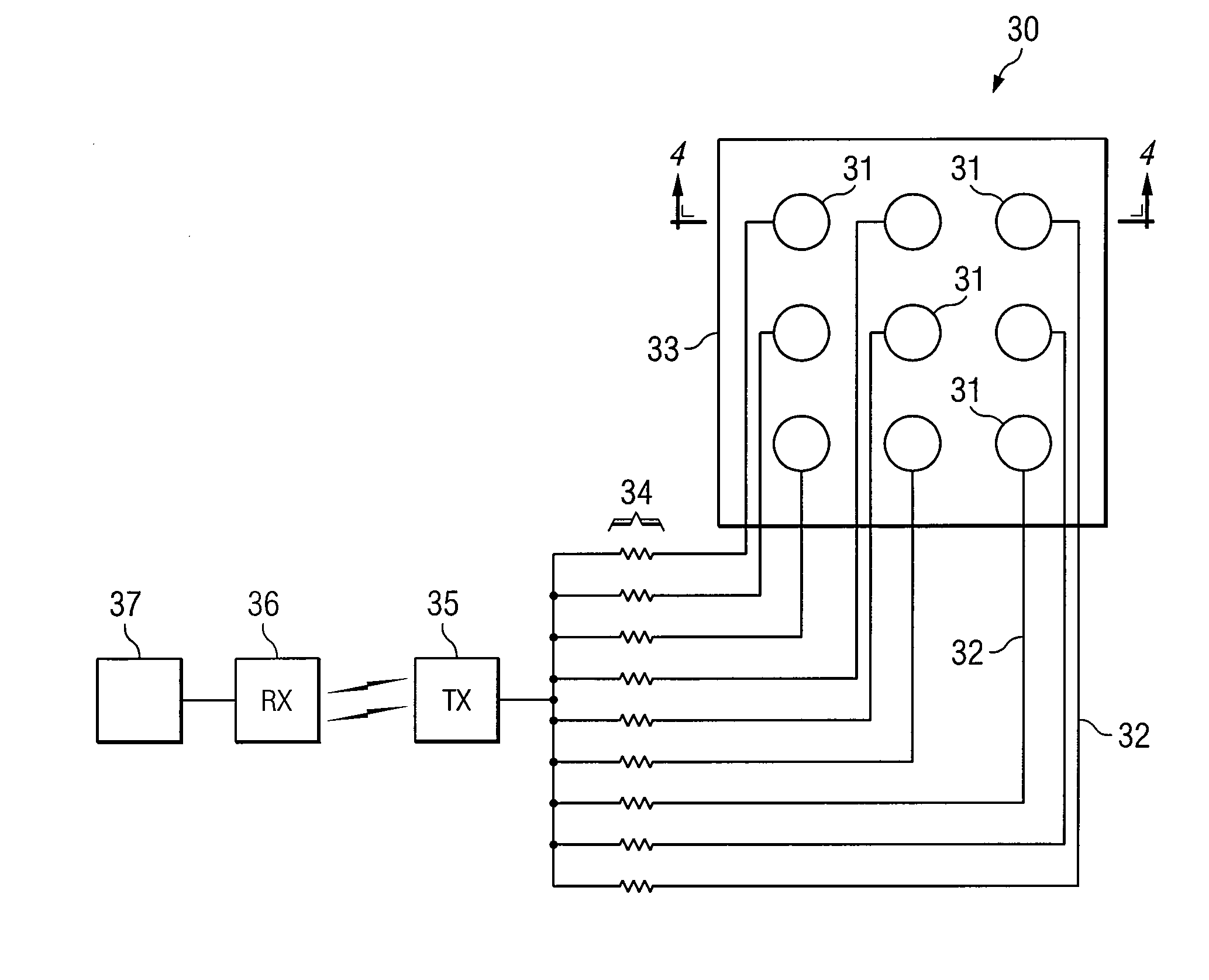
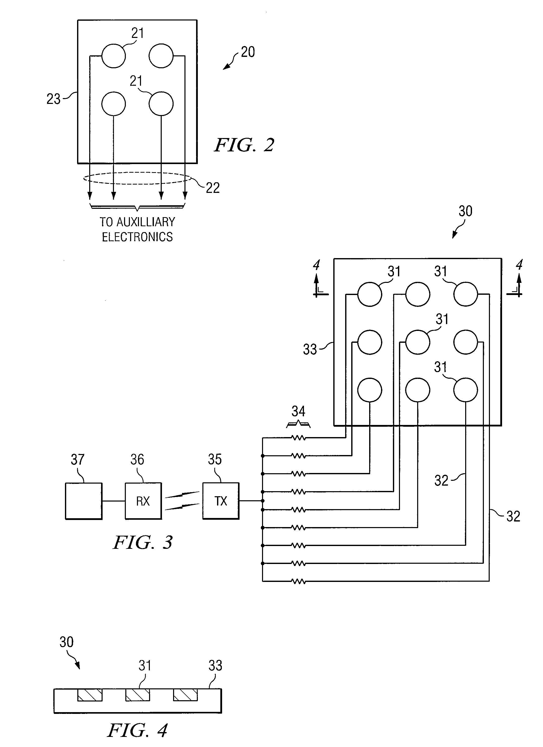
[0014] The following description is directed to a “coupled multi-electrode array sensor”, fabricated using techniques that result in a planarized sensor design. In other words, as compared to other multi-electrode sensor designs, the electrodes and leads are approximately planar, a result of being fabricated “bottom up” upon the same backing.

[0015] The design facilitates use of the sensor under paint or other coatings or under insulation, to detect corrosion of a metal surface under paint or some other type of coating, as well as in occluded regions (crevices) previously unreachable by coupled multielectrode array sensors. For purposes of this description, the sensor is described as being located in a “subsurface”, which means a location that is under or in a coating or under some other type of overlying material.

[0016] An advantage of the invention is that corrosion under a coating can be detected without the need to strip the coating. The sensor can be embedded under the coating...


PUM

PropertyMeasurementUnit
thicknessaaaaaaaaaa
sizeaaaaaaaaaa
corrosionaaaaaaaaaa

Abstract

A planarized type of coupled multi-electrode corrosion sensing device. Electrode pads are fabricated on a thin backing, such as a thin film. Each pad has an associated electrical lead for connection to auxiliary electronic circuitry, which may include a resistor associated with each electrical pad. The design permits the device to be easily placed in small crevices or under coatings such as paint.

Description

RELATED PATENT APPLICATION [0001] This application claims the benefit of U.S. Provisional Application No. 60 / 726,076, filed Oct. 12, 2005 and entitled “Planar Multi-Electrode Array Sensor For Localized Electrochemical Corrosion Detection.”GOVERNMENT LICENSE RIGHTS [0002] The U.S. Government has a paid-up license in this invention and the right in certain circumstances to require the patent owner to license others on reasonable terms as provided for by the terms of the United States Department of Energy Contract No. DE-FC26-04NT42267.TECHNICAL FIELD OF THE INVENTION [0003] This invention relates to sensors for detecting corrosion in electrically conductive materials, and more particularly to a multi-electrode sensor fabricated in thin-film form. BACKGROUND OF THE INVENTION [0004] Corrosion is a natural process, and at the molecular level, involves a metal atom M being oxidized. The atom loses one or more electrons and leaves the bulk metal, M->Mm++me−. The lost electrons are condu...

Claims


Application Information

Patent Timeline
Patent Type & Authority Applications(United States)
IPC IPC(8): G01N17/04G01N27/26
CPCC25D21/12G01N17/04G01N17/02
Inventor TORMOEN, GARTH WILLIAMBROSSIA, CHRISTOPHER SEAN
Owner SOUTHWEST RES INST
Why Eureka
Try Eureka