Structures and methods thereof for scanner with two CCD arrays

a technology of structure and method, applied in the field of structure and method of scanner, can solve the problems of slowing down scan speed, unfavorable scanning effect, and resolution of scanner, and achieve the effect of lowering scan time and elevating the quality of scanned imag

Inactive Publication Date: 2007-08-23
MICROTEK INT
View PDF3 Cites 24 Cited by
  • Summary
  • Abstract
  • Description
  • Claims
  • Application Information

AI Technical Summary

Benefits of technology

[0022]Consequently, the structures and methods thereof of the present invention for a scanner with t

Problems solved by technology

Therefore, the scanner needs to increase the exposure time to compensate, it will slow down the scan speed and this is an unwanted drawback.
However, the drawback of this kind of method to raise the scanner resolution is that it needs to scan twice, and so as to double the overall scan time.
However, the drawback of this kind of method to recovery the defects of the scanned image for the reflective media is that it needs to scan twice, and so as to do

Method used


Image

  • Structures and methods thereof for scanner with two CCD arrays
  • Structures and methods thereof for scanner with two CCD arrays
  • Structures and methods thereof for scanner with two CCD arrays

Examples


first embodiment

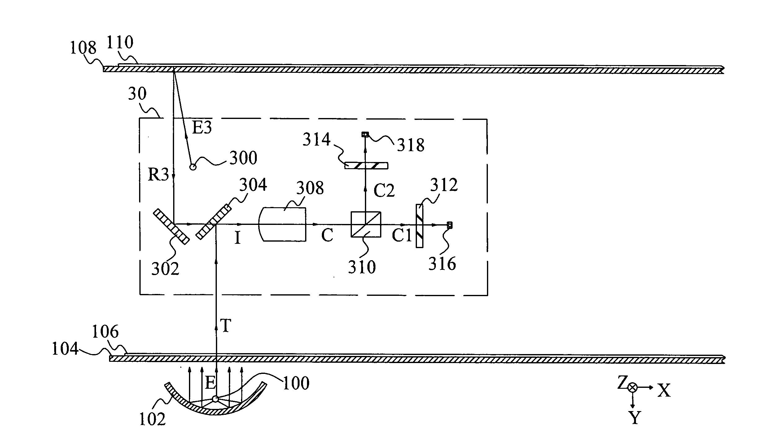
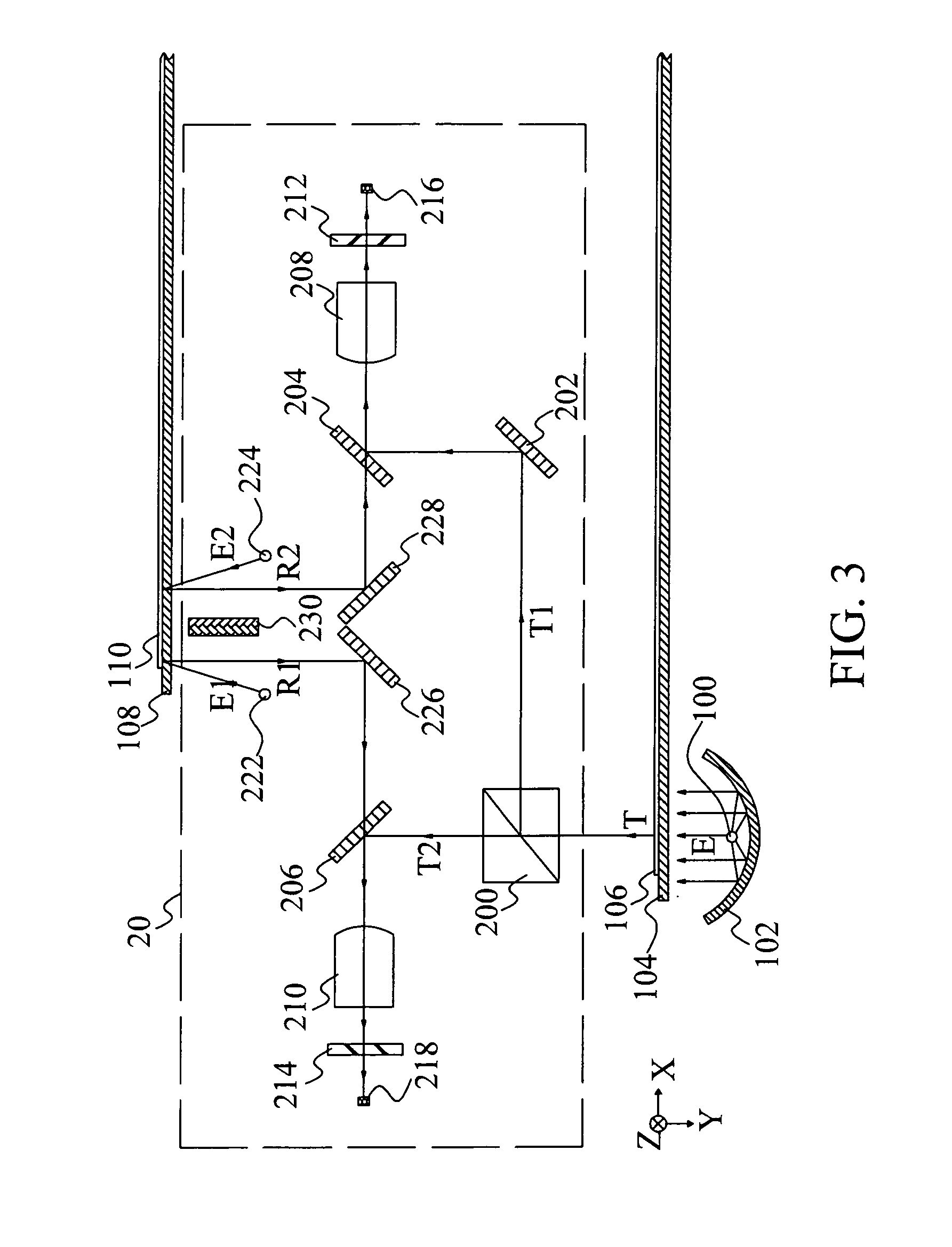
[0040]FIG. 3 is a schematic diagram of the scanner structure with two CCD arrays and two focus-image lenses which can scan the transparent media and the reflective media according to the present invention.

[0041]Firstly, the scan process for the transparent media is explained as followed. A transparent medium 106 is set on a transparent plate 104. In one preferred embodiment, transparent plate 104 can be a film holder to hold a scanned film at a scan position. A light-source 100, located below the glass plate 104, is composed of a Cold Cathode Fluorescent Lamp (CCFL) or its similar visible light-source and an Infrared Light Emitting Diode (IR-LED). The CCFL or its similar visible light-source and the IR-LED can be controlled to illuminate separately or simultaneously. The curved mirror 102 is used to reflect the back-light of the light-source 100 to enhance the intensity of the incident light “E” for the transparent medium 106, it can be omitted if the intensity of the light-source 1...

second embodiment

[0053]Firstly, the second embodiment is to explain the function of the image recovery of the present invention for the reflective medium 110. Please refer to FIG. 3 again. It can be understood from the previous description that the CCD arrays 216 and 218 respectively receive the reflective image beams which are originated from the two light-sources 222 and 224 and reflected on the surface of the reflective medium 110. After the scan action, the CCD arrays 216 and 218 respectively receive two independent images of the reflective medium 110. The incident lights “E1” and “E2” emitted from the light-sources 222 and 224 are located at two different sides of a normal, which is normal to the plane of the reflective medium 110 and between the two light-sources 222 and 224. It means that the two incident lights “E1” and “E2” have different incident angles. Therefore, the hetero-points such as the dust, pollutants, or scratches on the scanned object will form two different shadows on the scan...

third embodiment

[0054]The third embodiment is to explain the function of the image recovery of the present invention for the transparent medium 106, please refer to FIG. 3 again. The CCFL or its similar visible light-source and the IR-LED of the light-source 100 illuminate simultaneously and move along with the optical carriage 20 in the “X”-direction. The two switching filters 212 and 214, which are the visible-light filter and the IR-light filter respectively, are set in the optical routes. Therefore, the CCD arrays 216 and 218 respectively receive a visible-light image and an IR-light image of the transparent medium 106. Because the dyes are transparent and the hetero-points are relatively opaque to the IR light, thus the defects of the scanned image caused by the hetero-points for the transparent medium 106 can be recovered by comparing and processing the two scanned images of the CCD arrays 216 and 218, and then a recovered image can be stored or output.


PUM


Abstract

Structures and methods thereof for a scanner with two CCD arrays, which respectively capture two independent object images in one scan action, are provided. Three functions: a. image recovery, b. double resolution, and c. high dynamic range can be achieved for the transparent media and the reflective media. The image defects caused by the dust, pollutants, or scratches can be recovered by comparing the different shadows formed by two light-sources in two object images for the reflective media or comparing two object images formed respectively by a visible light-source and a infrared light-source for the transparent and reflective media. The function of double resolution can be achieved by making a relative displacement of half pixel-distance between two CCD arrays in their longitudinal direction. The function of high dynamic range can be achieved by setting two different exposure time for two CCD arrays.

Description

BACKGROUND OF THE INVENTION[0001]1. Field of the Invention[0002]The present invention relates to the structures and methods of a scanner, and more particularly, to the structures and methods with two CCD arrays which capture two independent object images in one scan action.[0003]2. Description of the Prior Art[0004]The image scanner is an apparatus to capture the object images and convert them into digital data which can be displayed, edited, stored, processed, and output by the computer.[0005]The scanned objects can be distinguished as the transparent media and reflective media. The transparent media are partial-transparent materials including the films, the slides, and the transparencies, etc. And the reflective media are opaque materials including the photographs, the paper documents, and the printed materials, etc. The Taiwan patent, patent No. 161970, discloses a scanner structure which can scan both the transparent media and the reflective media. Presently, the dual-mode scann...

Claims


Application Information

Patent Timeline
IPC IPC(8): G06K7/10
CPCG06K7/10792G06K7/10722
Inventor YANG, JIN-CHUNYEH, HARN-JOU
Owner MICROTEK INT
Why Eureka
Try Eureka