Light emitting apparatus and control method thereof

Inactive Publication Date: 2007-08-23
SAMSUNG ELECTRONICS CO LTD
View PDF4 Cites 19 Cited by
  • Summary
  • Abstract
  • Description
  • Claims
  • Application Information

AI Technical Summary

Benefits of technology

[0009]The present invention provides a light emitting apparatus which is capable of increasing the temperature of a light emitting part by supplying power to the light

Problems solved by technology

If an output voltage of the light emitting part is increased to meet the level of the initial increasing forward voltage drop of the light emitting part, an output voltage range of a voltage source of the light emitting apparatus increases, which may lead to difficulty in designing the apparatus, as well as an increase in prod

Method used


Image

  • Light emitting apparatus and control method thereof
  • Light emitting apparatus and control method thereof
  • Light emitting apparatus and control method thereof

Examples


Example

[0029]Reference will now be made in detail to exemplary embodiments of the present invention, examples of which are illustrated in the accompanying drawings.

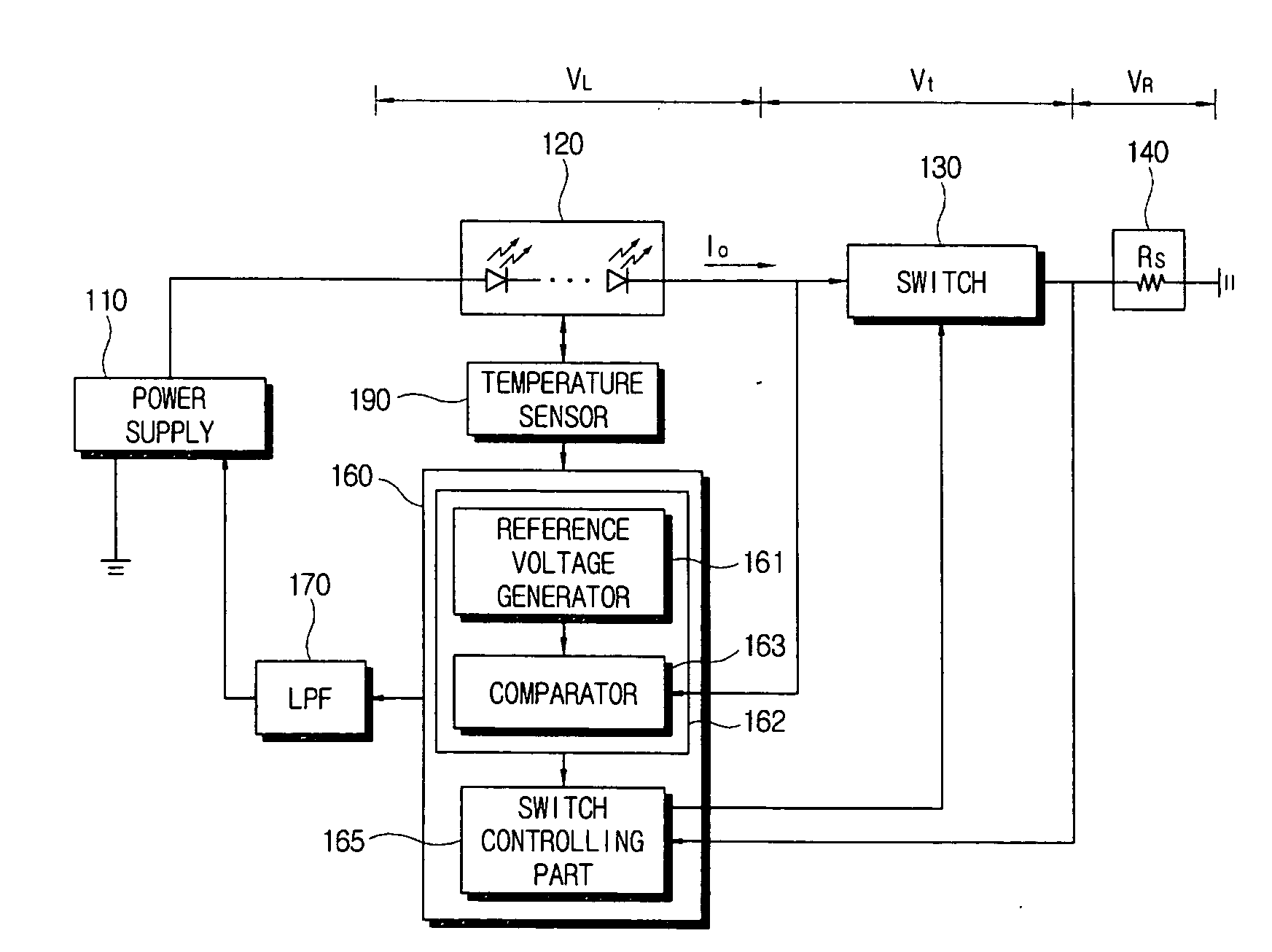
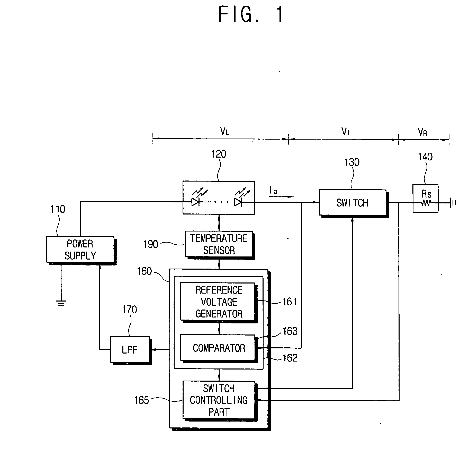
[0030]Referring to FIG. 1, a light emitting apparatus according to an exemplary embodiment of the present invention includes a light emitting part 120 which emits light, a power supply 110, a switch 130, and a controller 160 which controls these components. The light emitting apparatus may further include at least one of a temperature sensor 190 which senses the temperature of the light emitting part 120, a low pass filter (LPF) 170, and a current sensing resistor 140.

[0031]The power supply 110, which is a power source which supplies a constant voltage to the light emitting part 120, outputs variable power to the light emitting part 120 in order to maintain a constant driving voltage applied to the switch 130 by the controller 160. The power supply 110 may vary power from a level higher than a maximal voltage, which may be appli...


PUM


Abstract

A light emitting apparatus and control method are provided. The light emitting apparatus includes a light emitting part; a power supply which applies a voltage to the light emitting part; a switch which is connected in series with the light emitting part; and a controller which controls the power supply to maintain a current applied to the switch, to apply a first voltage level to the light emitting part for a reserve time when the light emitting part is initially driven, and to apply a second voltage level to the light emitting part after the reserve time elapses. The light emitting apparatus and control method increase the temperature of a light emitting part by supplying power to the light emitting part for a reserve time before the light emitting part is driven normally at an initial stage of driving the light emitting part.

Description

CROSS-REFERENCE TO RELATED APPLICATIONS[0001]This application claims priority from Korean Patent Application No. 2006-0016901, filed on Feb. 21, 2006 in the Korean Intellectual Property Office, the disclosure of which is incorporated herein by reference.BACKGROUND OF THE INVENTION[0002]1. Field of the Invention[0003]Apparatuses and methods consistent with the present invention relate to a light emitting apparatus and a control method thereof, and more particularly, to a light emitting apparatus which is capable of improving light-emission characteristics by controlling the sequence of driving a plurality of light emitting parts at an initial stage of driving the light emitting elements, and a control method thereof.[0004]2. Description of the Related Art[0005]Cathode ray tubes (CRTs) and flat panel displays (FPDs) are used as display apparatuses. A flat panel display mainly uses a liquid crystal display (LCD) panel or a plasma display panel (PDP). In addition, other types of display...

Claims


Application Information

Patent Timeline
IPC IPC(8): H01J40/14G01J1/44H03F3/08H05B44/00
CPCH03F3/08H03F2200/504H05B33/0818H05B33/0815H03F2200/78H05B45/3725G02F1/133
Inventor LEE, SANG-HOONKANG, JEONG-IL
Owner SAMSUNG ELECTRONICS CO LTD
Why Eureka
Try Eureka