Organic electroluminescent device

a technology of electroluminescent devices and organic materials, which is applied in the direction of discharge tube luminescnet screens, sustainable buildings, natural mineral layered products, etc., can solve the problems of reducing color reproducibility, chromaticity control, and affecting the quality of products, so as to achieve easy color adjustment and high luminous efficiency

Inactive Publication Date: 2007-08-23
IDEMITSU KOSAN CO LTD
View PDF7 Cites 31 Cited by
  • Summary
  • Abstract
  • Description
  • Claims
  • Application Information

AI Technical Summary

Benefits of technology

[0018] According to the invention, in a device comprising two emitting layers provided between an anode and a cathode, an organic EL device which easily adjusts colors and has a high luminous efficiency can be provided by utilizing both of fluorescent emission and phosphorescent emission.

Problems solved by technology

Chromaticity change in the white organic EL device not only impairs the quality of the product, but also causes decrease of color reproducibility in, for instance, a full-color display which is combined with color filters.
However, there are problems that such organic EL devices have difficulty controlling chromaticity and that they are poor in reproducibility.
Therefore, in order to obtain white light, a yellow-to-orange red dopant has to be used in a considerably diluted manner, so that there is a problem in the point of reproducibility.
However, in view of the problem that energy transmission depends upon distance, there has been a critical issue that extensive chromaticity change is observed after the organic EL device has been driven continuously or it has been kept under a high temperature condition.
This is the cause of chromaticity change.
For this, it is necessary for the thickness of the yellow-to-orange or red emitting layer to be made thinner than that of the blue emitting layer, or for the doping concentration of the yellow-to-orange or red emitting material to be lowered, so that fabrication of such a device is difficult.
Concretely, unless the thickness of the yellow-to-orange or red emitting layer is made approximately 1 to 2 nm, white light emission cannot be obtained in many cases.
Such a thickness is almost the same as the size of the molecules of ordinary low molecular type organic EL materials, and it is very difficult to control the thickness to this value.

Method used


Image

  • Organic electroluminescent device
  • Organic electroluminescent device
  • Organic electroluminescent device

Examples


example 1

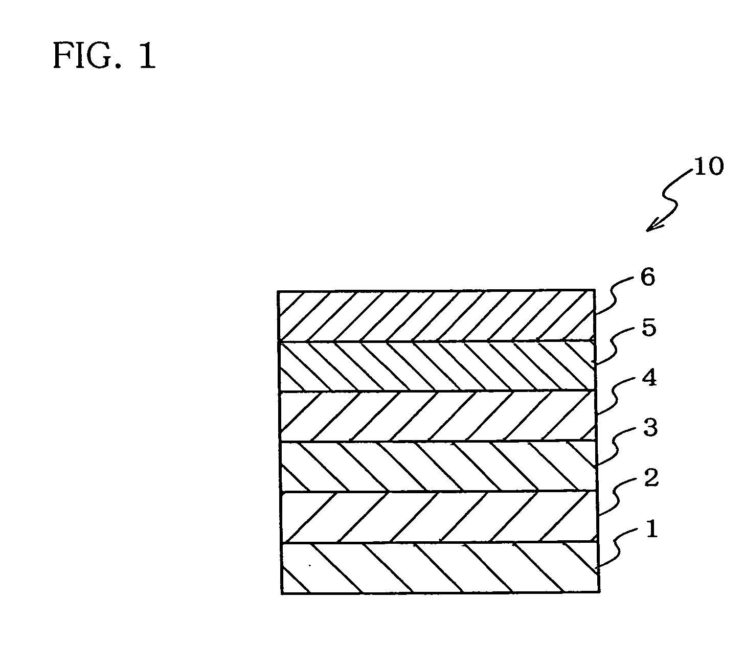
[0123] A 25 mm×75 mm and 1.1 mm thick glass substrate with an ITO transparent electrode (anode) (supplied by GEOMATEC CO., LTD.) was subjected to ultrasonic cleaning in isopropyl alcohol for 5 minutes and then subjected to UV ozone cleaning for 30 minutes.

[0124] The cleaned glass substrate with transparent electrode lines was fitted to a substrate holder of a vacuum vapor deposition apparatus. First, a 60 nm thick film of N,N′-bis(N,N′-diphenyl-4-aminophenyl)-N,N-diphenyl-4,4′-diamino-1,1′-biphenyl (to be abbreviated as “TPD232 film” hereinafter) was formed on the surface thereof on which the transparent electrode lines were formed so as to cover the above transparent electrode. The TPD 232 film functioned as a hole-injecting layer.

[0125] The formation of the TPD232 film was followed by formation of a 20 nm thick film of 4,4′-bis[N-(1-naphthyl)-N-phenylamino]biphenyl (to be abbreviated as “NPD film” hereinafter) on the TPD232 film. The NPD film functioned as a hole-transporting la...

example 2

[0131] A device was fabricated by the same method as in Example 1 except that a compound represented by formula was used instead of CBP.

[0132] The above device had a luminance of 100 cd / m2 and an efficiency of 13 cd / A at a DC voltage of 7.5 V as an initial performance. Light from the device has CIE1931 chromaticity coordinates of (x,y)=(0.293, 0.282) and was white.

example 3

[0133] A device was fabricated by the same method as in Example 1 except that a compound represented by formula

[0134] as a host compound and a compound represented by formula [36] as a dopant compound were used instead of formulas [31] and [32].

[0135] The above device had a luminance of 100 cd / m2 and an efficiency of 16 cd / A at a DC voltage of 7.3 V. Light from the device has CIE1931 chromaticity coordinates of (x,y)=(0.292, 0.280) and was white.


PUM

PropertyMeasurementUnit
electron mobilityaaaaaaaaaa
hole mobilityaaaaaaaaaa
thicknessaaaaaaaaaa

Abstract

An organic EL device which can easily control colors to obtain white light emission, and has a high efficiency. An organic electroluminescent device 10 including; at least an anode 1, an organic emitting layer and a cathode 6 stacked in this order; at least a first emitting layer 3 including a fluorescent dopant and a second emitting layer 4 comprising a phosphorescent dopant being stacked in the organic emitting layer.

Description

TECHNICAL FIELD [0001] The invention relates to an organic electroluminescent device. In more detail, the invention relates to an organic electroluminescent device comprising two emitting layers suitable for white emission. TECHNICAL BACKGROUND [0002] Recently, white organic electroluminescent (EL) devices are being actively developed because they can be used for a mono-color display device, a lighting apparatus such as a back light, and a full-color display with color filters. [0003] Chromaticity change in the white organic EL device not only impairs the quality of the product, but also causes decrease of color reproducibility in, for instance, a full-color display which is combined with color filters. Therefore, minimal chromaticity change is required for the white organic EL devices. [0004] Many methods of producing white light emission by an organic EL device have been disclosed. Few of the methods produce white light with only one kind of emitting material and a single organic ...

Claims


Application Information

Patent Timeline
Patent Type & Authority Applications(United States)
IPC IPC(8): H01L51/50C09K11/06H01L51/00H05B33/12H05B33/14
CPCC09K11/06Y02B20/181C09K2211/1011C09K2211/1029C09K2211/1044C09K2211/1048C09K2211/1096H01L51/0052H01L51/0056H01L51/0059H01L51/006H01L51/0071H01L51/0072H01L51/0085H01L51/5016H01L51/5036H05B33/14C09K2211/1007Y02B20/00H10K85/615H10K85/624H10K85/631H10K85/633H10K85/657H10K85/342H10K85/6572H10K50/125H10K50/11H10K2101/10H05B33/12
Inventor ITO, MITSUNORIMATSUURA, MASAHIDEYAMAMOTO, HIROSHIKAWAMURA, HISAYUKIHOSOKAWA, CHISHIO
Owner IDEMITSU KOSAN CO LTD
Why Eureka
Try Eureka