Charging apparatus for capacitor storage type power source and discharging apparatus for capacitor storage type power source

a technology of capacitor storage and charging apparatus, which is applied in the direction of charging equalisation circuit, transportation and packaging, and the arrangement of several simultaneous batteries, etc., can solve the problems of reducing the efficiency of the discharging apparatus, and requiring a long charge time. , to achieve the effect of reducing the leak current, reducing the amount of heat generated by the discharging apparatus, and reducing the amount of heat generated

a technology of capacitor storage and charging apparatus, which is applied in the direction of charging equalisation circuit, transportation and packaging, and the arrangement of several simultaneous batteries, etc., can solve the problems of reducing the efficiency of the discharging apparatus, and requiring a long charge time. , to achieve the effect of reducing the leak current, reducing the amount of heat generated by the discharging apparatus, and reducing the amount of heat generated

US20070194759A1Inactive Publication Date: 2007-08-23POWER SYST KK

Image

  • Charging apparatus for capacitor storage type power source and discharging apparatus for capacitor storage type power source
  • Charging apparatus for capacitor storage type power source and discharging apparatus for capacitor storage type power source
  • Charging apparatus for capacitor storage type power source and discharging apparatus for capacitor storage type power source

Examples


Embodiment Construction

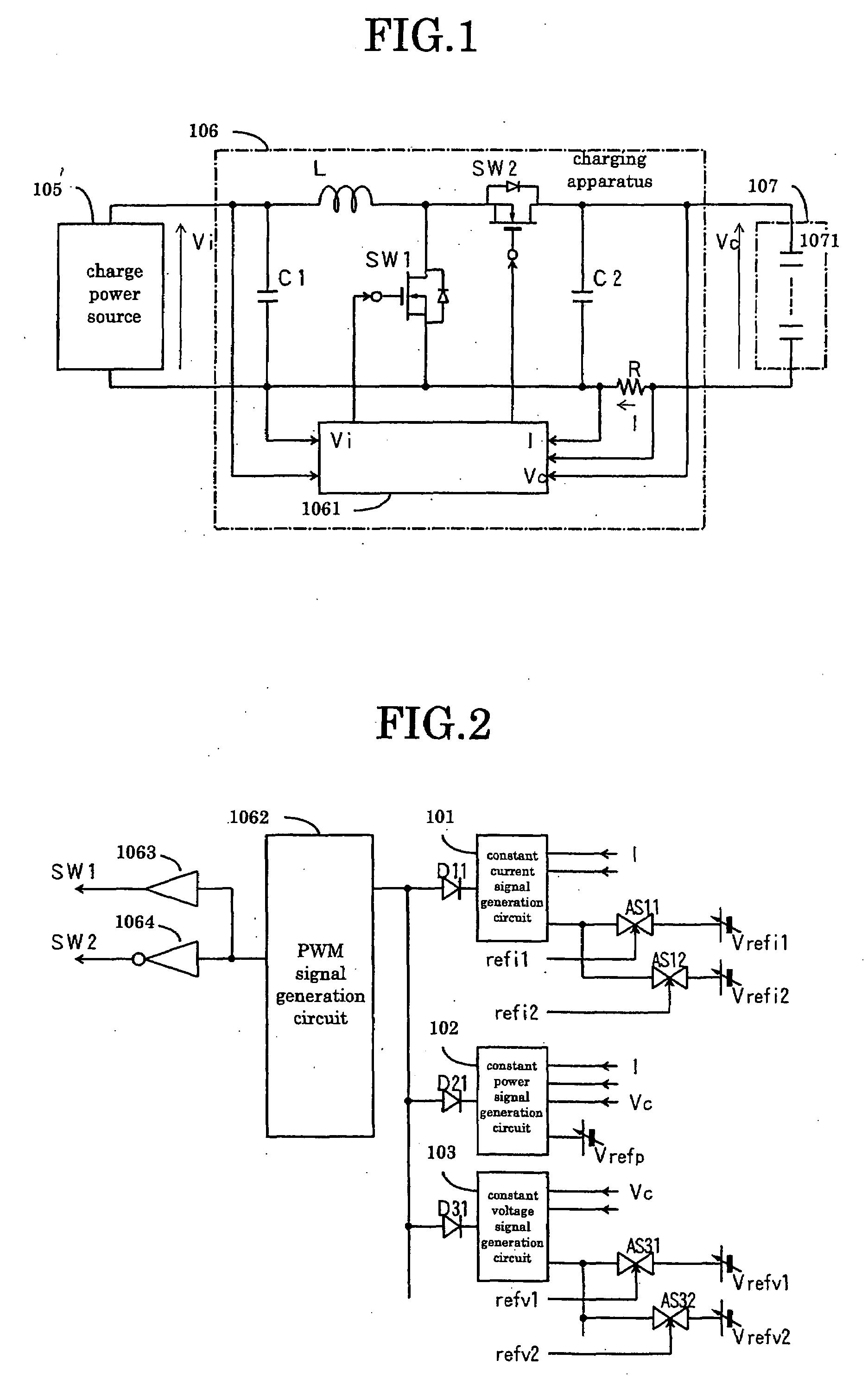
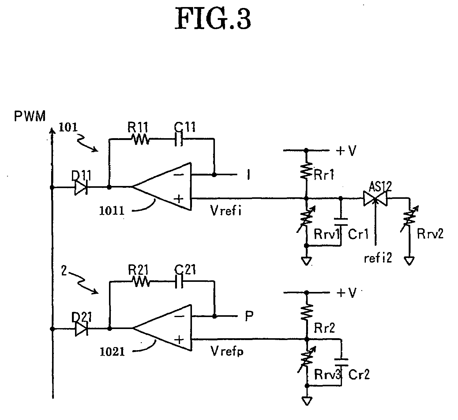
[0179](On the first aspect of the invention) Now, the present invention will be described by referring to the accompanying drawings that illustrate preferred embodiments of the invention. FIG. 1 is a circuit diagram of the main circuit of an embodiment of charging apparatus for a capacitor storage type power source according to the present invention and FIG. 2 is a circuit diagram of the signal processing circuit of an embodiment of charging apparatus for a capacitor storage type power source. Referring to FIGS. 1 and 2, there are shown a constant current signal generation circuit 101, a constant power signal generation circuit 102, a constant voltage signal generation circuit 103, a charge power source 105, a charging apparatus 106, a capacitor storage type power source 107, a signal processing circuit 1061, a PWM signal generation circuit 1062, an amplifier 1063, an inverting amplifier 1064, electric double layer capacitors 1071, analog switches AS11, AS12, AS21, AS22, capacitors ...


PUM


Abstract

A charging apparatus for electrically charging a capacitor storage type power source comprises a switching circuit for turning on / off the charge current, a current detection circuit for detecting the charge current, a voltage detection circuit for detecting the voltage of power source, a constant current control circuit for outputting an error amplifying signal according to the current value, a power control circuit for outputting an error amplifying signal according to the current value, the voltage value-and a power reference value, a constant voltage control circuit for outputting an error amplifying signal according to the voltage value and a voltage reference value, an OR circuit for selecting one of the error amplifying signals and a control circuit for generating a pulse width modulation signal according to the error amplifying signal output from the OR circuit to turn on / off the switching circuit and control the charge current.

Description

CROSS-REFERENCE TO RELATED APPLICATIONS[0001]This patent application is based upon and claims the benefit of priority from the prior Japanese Patent Applications No. 2006-040764 filed on Feb. 17, 2006, No. 2006-042000 filed on Feb. 20, 2006, No. 2006-042001 filed on Feb. 20, 2006, No. 2006-043335 filed on Feb. 21, 2006, No. 2006-081999 filed on Mar. 24, 2006, No. 2006-082096 filed on Mar. 24, 2006, No. 2006-083402 filed on Mar. 24, 2006, No. 2006-113987 filed on Apr. 18, 2006, No. 2006-209849 filed on Aug. 1, 2006 and No. 2006-231485 filed on Aug. 29, 2006, the entire contents of which are incorporated herein by reference.BACKGROUND OF THE INVENTION[0002](On the first aspect of the invention) This invention relates to a charging apparatus for a capacitor storage type power source for electrically charging a capacitor storage type power source storing electric energy in electric double layer capacitors.[0003]The terminal voltages can fluctuate to a large extent in a high voltage and ...

Claims


Application Information

Patent Timeline
23 Aug 2007
Publication
US20070194759A1
IPC
H02J7/00
CPC
H02J7/0016; H02J7/345; H02J7/0065; H02J2207/20
Inventors
SHIMIZU, MASAAKI; MITSUI, KATSUJI