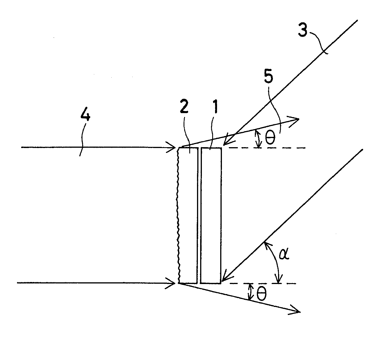
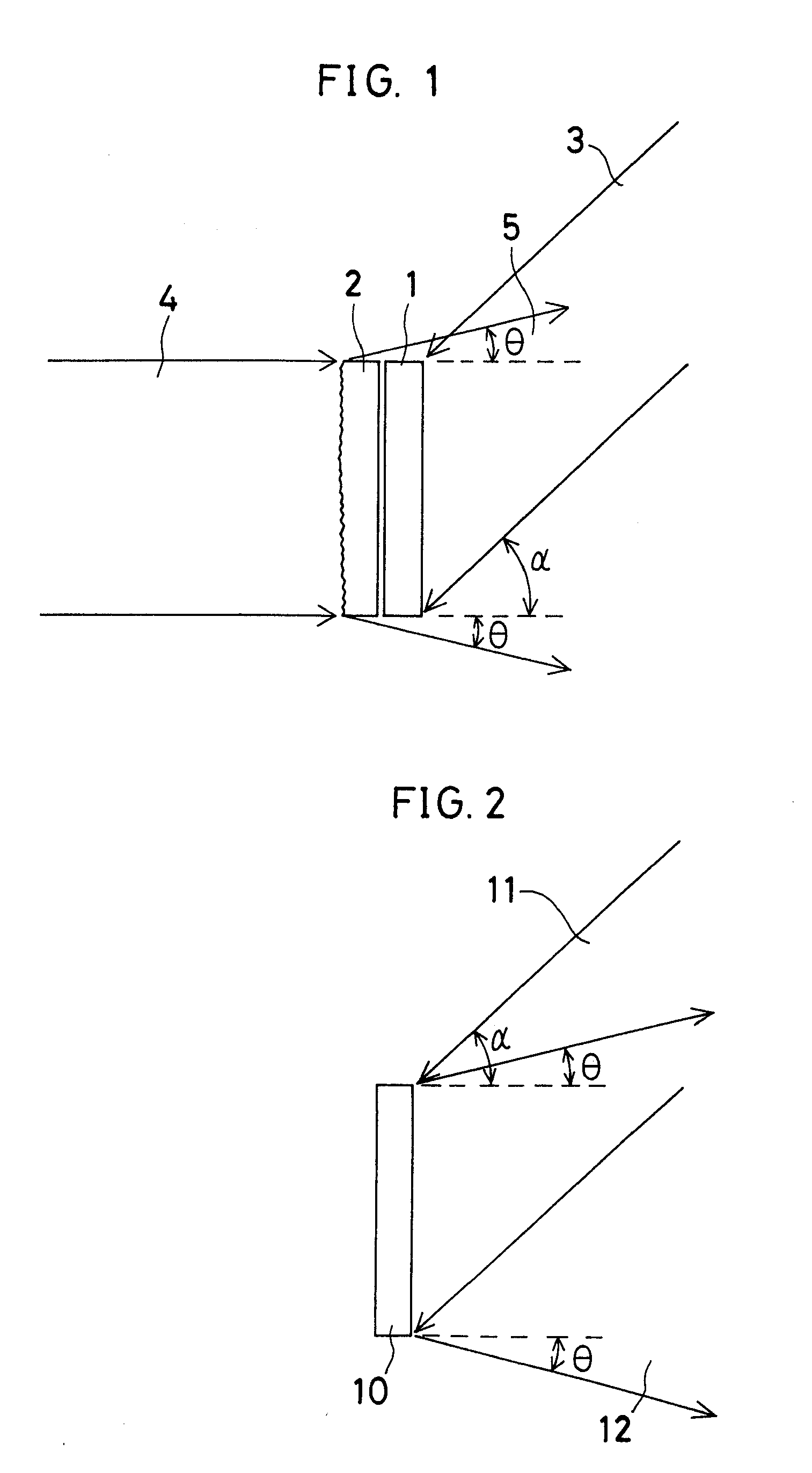
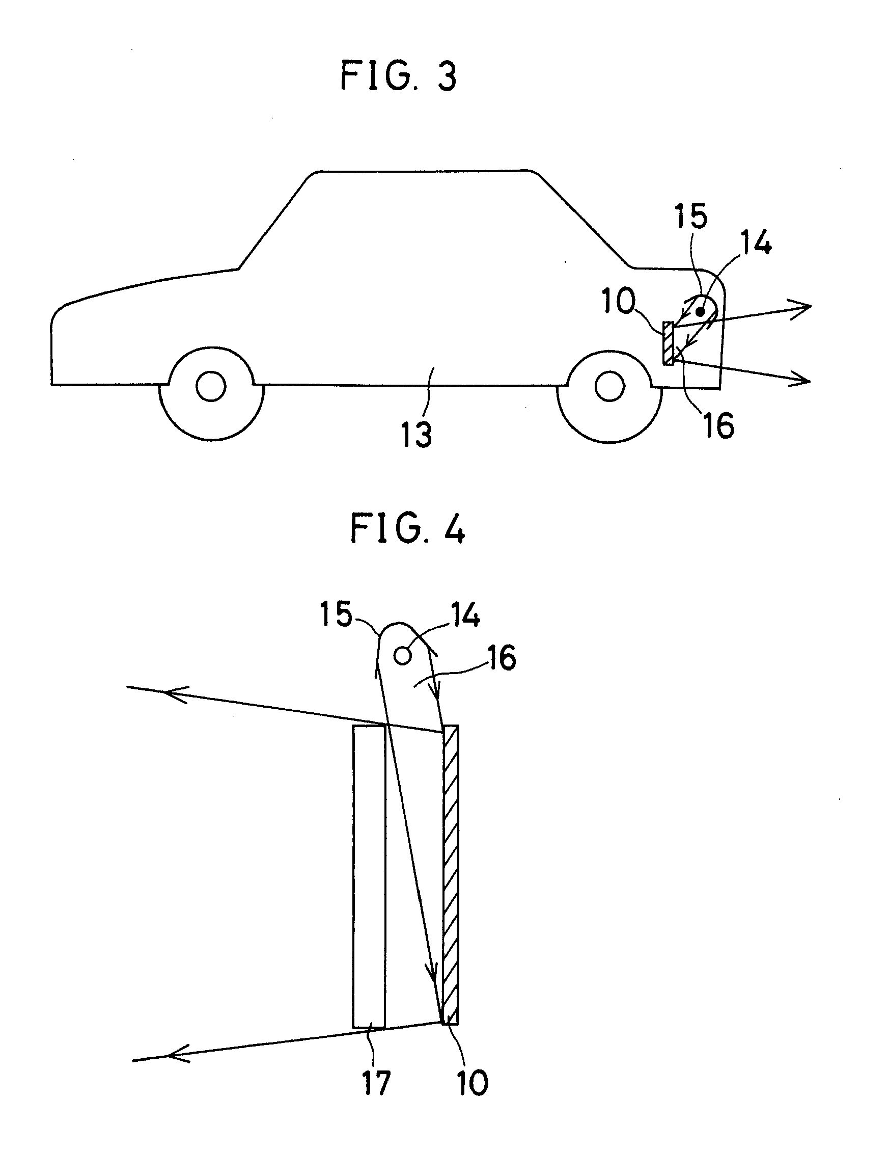
Reflection type diffuse hologram, hologram for reflection hologram color filters, etc, and reflection type display device using such holograms

a technology of reflection hologram and display device, which is applied in the direction of holographic process, optics, instruments, etc., can solve the problems of wasteful illumination light loss, inability to diffract, and wasteful illumination light consumption

Inactive Publication Date: 2007-08-23
DAI NIPPON PRINTING CO LTD
View PDF20 Cites 29 Cited by
  • Summary
  • Abstract
  • Description
  • Claims
  • Application Information

AI Technical Summary

Benefits of technology

[0017] In view of such problems associated with the prior art, it is an object of the present invention to provide a diffusing plate which can use a hologram to limit the angle of diffusion within a desired range, and makes bright display, etc possible.

Problems solved by technology

So far, scattering characteristics have been imparted to backlight by use of beads or the like, but a problem with this is that too large an angle of diffusion results in wasteful illumination light loss.
That is, although too large a diffusion angle is not required in view of the positional relation to succeeding cars, light from these lamps is not only wastefully consumed but also becomes dark because lenses positioned in front of the lamps cause the light to be diffused at an angle larger than required.
However, when surrounding ambient light alone is used as illumination light, this hologram color filter cannot diffract, and collect its wavelength components into desired positions.
In other words, this hologram color filter can never be applied to a direct-view type of liquid crystal display device or other like device in which surrounding ambient light is used as illumination light, or any particular backlight source is not required.
However, one problem with the aforesaid method is that it is not always easy to precisely control the quantity of light to develop a given color, and another possible problem is that the reproducibility of the color reconstructed is not stable.

Method used


Image

  • Reflection type diffuse hologram, hologram for reflection hologram color filters, etc, and reflection type display device using such holograms
  • Reflection type diffuse hologram, hologram for reflection hologram color filters, etc, and reflection type display device using such holograms
  • Reflection type diffuse hologram, hologram for reflection hologram color filters, etc, and reflection type display device using such holograms

Examples


first embodiment

[0177]FIG. 24 illustrates the principle of the hologram color display medium of the invention. FIG. 24(a) is a plan view of a swelling film 131 to be in close contact with the surface side of the material, and FIG. 24(b) is a plan view of a swelling film 132 to be in close contact with the back side of the material. Each film may have been obtained by mixing a monomer or oligomer, a photopolymerization initiator, etc. with a binder polymer, as in the case of a photopolymer. An area 131n occupying the right ⅔ of the swelling film 131 to be into close contact with the surface side of the material, and an area 132n occupying the right ⅓ of the swelling film 132 to be into close contact with the back side of the material have been deactivated by exposure to light in a quantity sufficient to make inert substantially all of the penetrating active monomer or oligomer in the swelling films. In other words, the swelling film 131 is active in an area 131a occupying the left ⅓ thereof, while t...

second embodiment

[0180]FIG. 25 illustrates the principle of the hologram color display medium of the present invention. FIG. 25(a) is a plan view of a swelling film 131 which is to be first brought into close contact with the surface side of the material for swelling. An area 131 occupying the right ½ of the swelling film 131 has been deactivated by exposure to light, as in the case of FIG. 24.

[0181] Then, as shown in FIG. 25(b), the swelling film 131 with the area 131n deactivated according to a constant deactivation pattern as depicted in FIG. 25(a) is brought into close contact with the surface of a volume hologram 130 previously obtained by recording plane interference fringes in a photopolymer or other photosensitive material at a constant pitch. The stack is heated under temperature, and time conditions sufficient to diffuse the penetrating active monomer or oligomer from the swelling film 131 into the volume hologram 130.

[0182] Another swelling film 132 such as one shown in FIG. 25(c) is pro...


PUM

PropertyMeasurementUnit
angle of diffusionaaaaaaaaaa
hazeaaaaaaaaaa
angleaaaaaaaaaa

Abstract

A method of fabricating a hologram having a pattern made up of pixels in which a photosensitive material for forming a hologram is stacked on either a reflection-type hologram or a transmission type hologram. According to one aspect of the invention, the photosensitive material is stacked on a reflection-type relief hologram and reconstructing illumination light of a given wavelength is struck on the reflection-type relief hologram through the photosensitive material, so that interference fringes produced by interference of the light diffracted from the reflection type relief hologram and the incident light are recorded in the photosensitive material. According to another aspect of the invention, the photosensitive material is stacked on a transmission-type hologram, and reconstructing illumination light of a given wavelength is struck on a side of the transmission type hologram that is not opposite to the volume hologram photosensitive material, so that interference fringes produced by interference of light diffracted from the transmission type hologram and reference light incident on the photosensitive material are recorded in the photosensitive material. According to a third aspect of the invention, the photosensitive material is stacked on a transmission type hologram, and reconstructing illumination light of a given wavelength is struck on a side of the transmission type hologram that is not opposite to the photosensitive material, so that interference fringes produced by interference of light diffracted from the transmission type hologram and zero-order transmitted light are recorded in the photosensitive material, and a reflecting layer is provided on a back side of the photosensitive material.

Description

CROSS REFERENCE TO RELATED APPLICATIONS [0001] This is a divisional of application Ser. No. 09 / 116,589 filed Jul. 16, 1998, which is a Continuation in Part of application Ser. No. 08 / 839,666 filed Apr. 15, 1997. The entire disclosures of the prior applications are hereby incorporated by reference.BACKGROUND OF THE INVENTION [0002] The present invention relates to a reflection type diffuse hologram that can be used for display devices such as liquid crystal display devices, a hologram for reflection hologram color filters, etc., and a reflection type display device using such holograms. [0003] Backlight used with a liquid crystal display device should have some scattering characteristics, so that the display device can have a wide viewing angle. So far, scattering characteristics have been imparted to backlight by use of beads or the like, but a problem with this is that too large an angle of diffusion results in wasteful illumination light loss. [0004] This is also true of an automo...

Claims


Application Information

Patent Timeline
Patent Type & Authority Applications(United States)
IPC IPC(8): G02B5/32G02B5/20G02F1/1335G03H1/18G03H1/24G03H1/28G03H1/30
CPCG02B5/0252G03H2270/24G02B5/32G02F1/133553G02F2203/03G03H1/0248G03H1/18G03H1/182G03H1/202G03H1/24G03H1/28G03H1/30G03H2001/0415G03H2001/0417G03H2001/186G03H2001/187G03H2001/2263G03H2001/263G03H2210/20G03H2222/13G03H2223/12G03H2223/14G03H2250/44G03H2260/12G02B5/203G03H1/2202
Inventor NISHIKAWA, SHINGOUEDA, KENJISEGAWA, TOSHIKAZUHOTTA, TSUYOSHIKUWABARA, YUKOWATANABE, MASACHIKA
Owner DAI NIPPON PRINTING CO LTD
Why Eureka
Try Eureka