
Method for detecting a response of each probe zone on a test strip

a technology of probe zones and test strips, applied in chemical methods analysis, instruments, analysis using chemical indicators, etc., can solve the problems of time-consuming and laborious procedures, expensive equipment, and inability to detect the response of each probe zone on the test strip, so as to achieve accurate and rapid determination

Inactive Publication Date: 2007-08-23
INTELLECTUAL VENTURES I LLC
View PDF73 Cites 9 Cited by
  • Summary
  • Abstract
  • Description
  • Claims
  • Application Information

AI Technical Summary

Benefits of technology

The present invention provides a method for detecting a response of each probe zone on a test strip, which can capture a whole image of the test strip and use the image position of the bottom edge of the test strip as a reference to identify the image positions of the responses of the probe zones. The responses of the probe zones can be accurately and rapidly determined in accordance with the gray levels of the related image positions. The method is quick and convenient to use by non-sophisticated personnel in non-laboratory settings, and performs assays for multiple drugs of abuse simultaneously. The method associates with an image capturing / processing technology to analyze drug residues in physiological fluid to attain the purposes of accuracy, rapid and cost effective in drug abuse detection technology.

Problems solved by technology

The procedure is tedious, time consuming and requires skilled personnel to interpret the results.
The laboratory test requires trained technicians to perform and the equipment necessarily costs several thousands of dollars.
However, the necessary equipment is expensive and the procedure is complicated.
Consequently, the testing procedure is necessarily expensive.
However, it is not convincing for concluding the test subject has used abuse-type drugs.

Method used


Image

  • Method for detecting a response of each probe zone on a test strip
  • Method for detecting a response of each probe zone on a test strip
  • Method for detecting a response of each probe zone on a test strip

Examples


Embodiment Construction

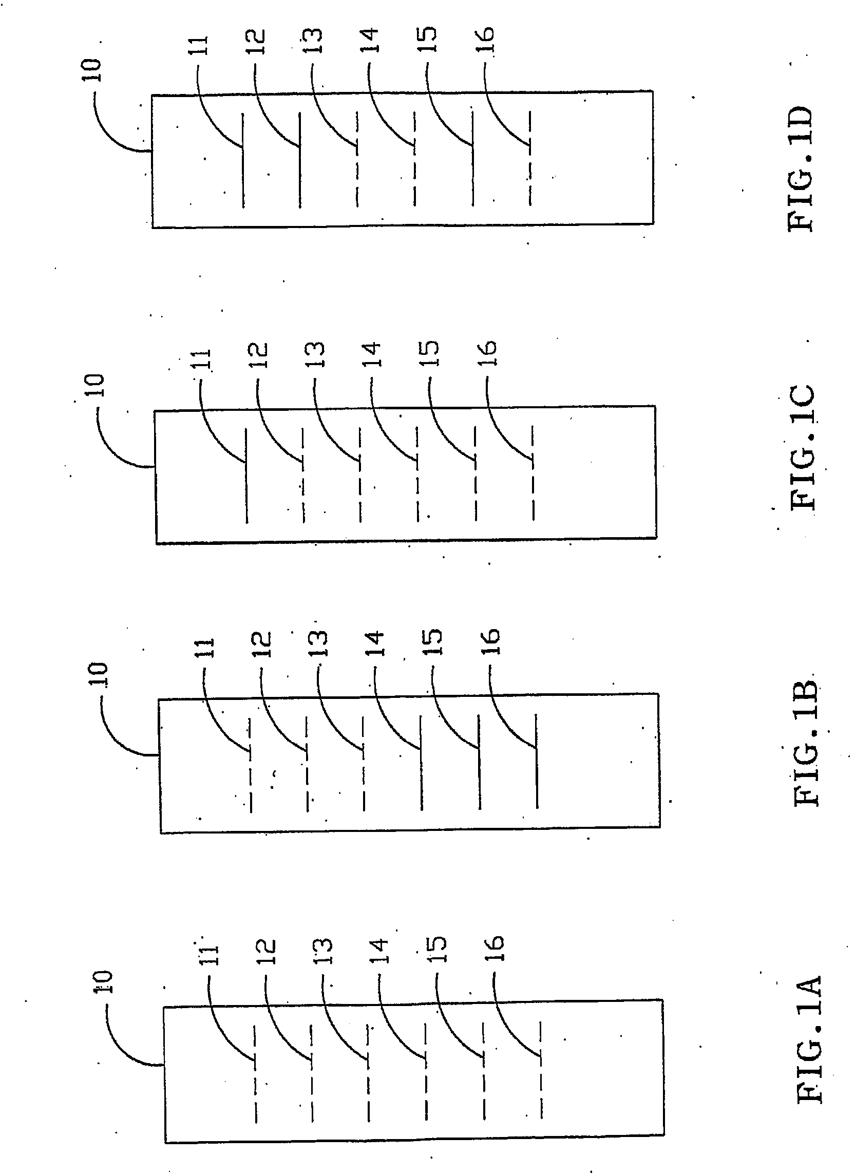
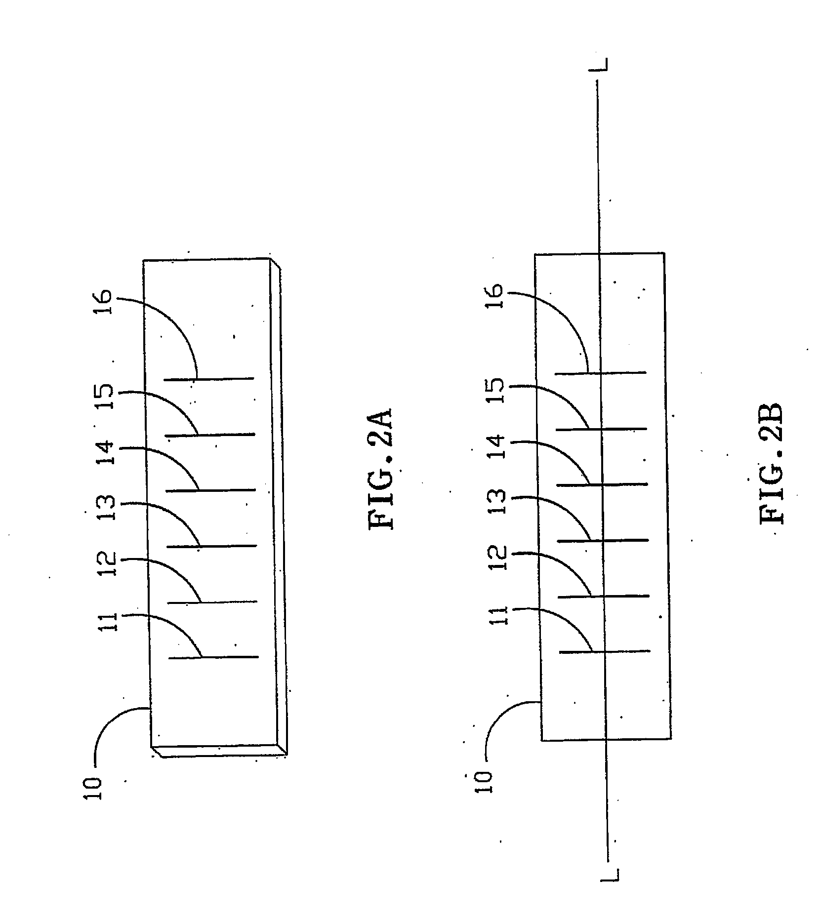
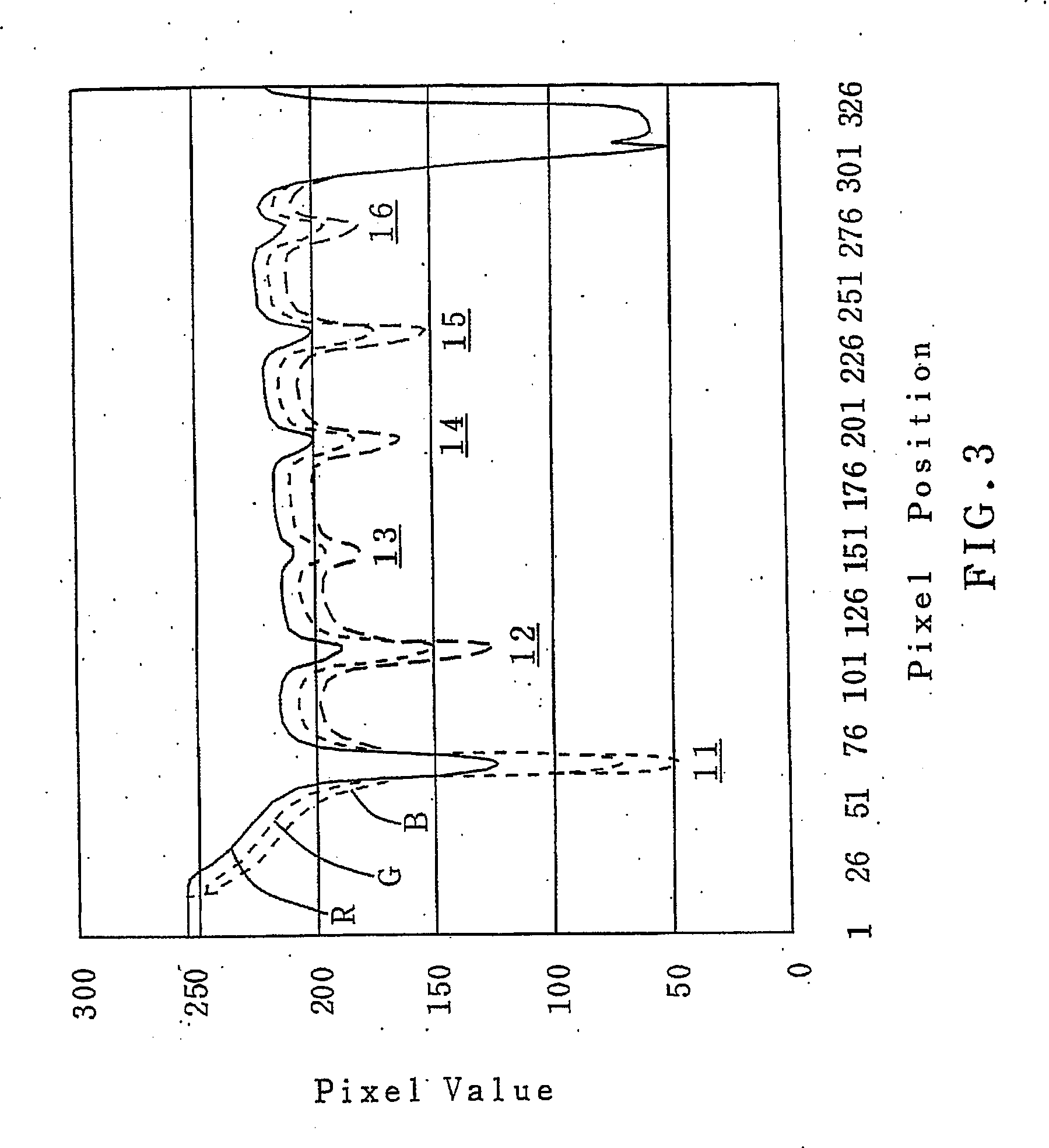
[0022] From a view of broad application, the present invention provides a method for detecting a response for each probe zone on a test strip after testing a sample solution, which associates with an image capturing / processing technology to detect respective responses of the probe zones on the test strip to qualitatively and quantitatively identify specific substances in the sample solution. More specifically, the present invention utilizes the image capturing technology to capture the whole image of a test strip having a color pattern displayed thereon. The color pattern includes a plurality of color lines each of which representing a probe zone of the test strip having a color change in response to a specific substance in the sample solution. In accordance with the image of the color pattern of the test strip, the response of each probe zone of the test strip to the sample solution can be determined so as to detect the presence or absence of the specific substance related to in th...


PUM

PropertyMeasurementUnit
coloraaaaaaaaaa
color changeaaaaaaaaaa
Thin layer chromatographyaaaaaaaaaa

Abstract

A method for detecting a response of each probe zone on a test strip is provided. The present method includes providing a test strip having a color pattern displayed thereon. The color pattern occurs in response to a tested solution contacting with the test strip and including a plurality of color lines displayed in sequence from a bottom portion of the test strip to a top portion thereof. The site of each color line represents a probe zone of the test strip. Capturing a whole image of the test strip and selecting at least one scan line perpendicular to the image of the color lines therefrom. Setting a pixel position of the scan line having a minimum pixel value corresponding to a bottom edge of the test strip and using the pixel position as a reference to identify respective pixel positions of the color lines on the scan line so as to identify the image positions thereof on the whole image. A response of each probe zone of the test strip related to a gray level of a corresponding image position is thus obtained.

Description

BACKGROUND OF THE INVENTION [0001] 1. Field of the Invention [0002] The present invention relates to a method for detecting a response of each probe zone on a test strip, and more particularly to a method for detecting a response of each probe zone on a test strip via an image capturing technology. [0003] 2. Description of the Prior Art [0004] Over the past decade, there has been an increased need and demand for analysis of various biological specimens, for purposes ranging from pregnancy testing to drug analysis. Considerable time and effort has been expended by way of devising systems and analytic techniques to ensure reliable testing and accurate results. [0005] Moreover, with increasing rise in the use of abuse-type drugs, the need for detecting and identifying those drugs and their metabolites is becoming more important. With this need, many more tests are required to monitor the use of abuse-type drugs. [0006] Thin layer chromatography (TLC) screening procedures for detecting ...

Claims


Application Information

Patent Timeline
Patent Type & Authority Applications(United States)
IPC IPC(8): G01N33/53G06F19/00G06T7/00G01N21/27G01N21/86G06K9/00
CPCG01N21/27Y10S435/805G01N21/8483
Inventor WANG, KUO-JENG
Owner INTELLECTUAL VENTURES I LLC
Learn More