Medical fluid injection and inflation system

a technology of which is applied in the field of combined fluid injection and inflation system, can solve the problems of not being able to provide accurate pressure sensing information, and achieve the effects of reducing the cost per patient, increasing the operator's sense of control, and varying the degree of tactile feel

Inactive Publication Date: 2007-08-23
BAYER HEALTHCARE LLC
View PDF48 Cites 108 Cited by
  • Summary
  • Abstract
  • Description
  • Claims
  • Application Information

AI Technical Summary

Benefits of technology

[0018] In general, the invention is a system that provides multiple fluid delivery modes including a fluid injection mode and a balloon inflation mode, obviating the need for multiple and separate pieces of equipment to perform these functions. In addition, it allows for coordinated or automated synchronization of fluid injection, balloon inflation, and aspiration. Balloon inflation may be performed for a lower cost per patient since the system is reusable, with the exception of a few inexpensive per-patient disposable components. Unlike the prior art devices discussed previously, the human operator has active, continuous control of the system, for example, through the use of a hand controller that allows for single-handed operation. The operator may continuously operate the system based on real-time fluid parameter feedback data provided to the operator. The system provides a level of tactile feedback to the operator increasing the operator's sense of control. Also, the system allows a “sensitivity adjustment” that varies the degree of tactile feel. Additionally, higher fluid pressures and flow rates may be obtained in the present system than can be achieved by hand syringes. Further, a large reservoir may be used and the system may be configured for automatic loading and reloading so that the system fluid path may remain closed for multiple injections, so as to lessen or eliminate the possibility of introducing air into the fluid path which may be harmful to the patient. Moreover, the system is adapted to support programmed limits and indicators for flow, volume, and pressure when injecting or inflating fluid even while the operator uses an operator control such as a hand controller or foot controller.

Problems solved by technology

One drawback with the system disclosed by this patent is the location of the control pressure transducer, which is specifically located between the pump drive mechanism and pump and is not likely to provide accurate pressure sensing information.

Method used


Image

  • Medical fluid injection and inflation system
  • Medical fluid injection and inflation system
  • Medical fluid injection and inflation system

Examples


Embodiment Construction

[0047] For purposes of the description hereinafter, spatial orientation terms, if used, shall relate to the referenced embodiment as it is oriented in the accompanying drawing figures or otherwise described in the following detailed description. However, it is to be understood that the embodiments described hereinafter may assume many alternative variations and embodiments. It is also to be understood that the specific devices illustrated in the accompanying drawing figures and described herein are simply exemplary and should not be considered as limiting.

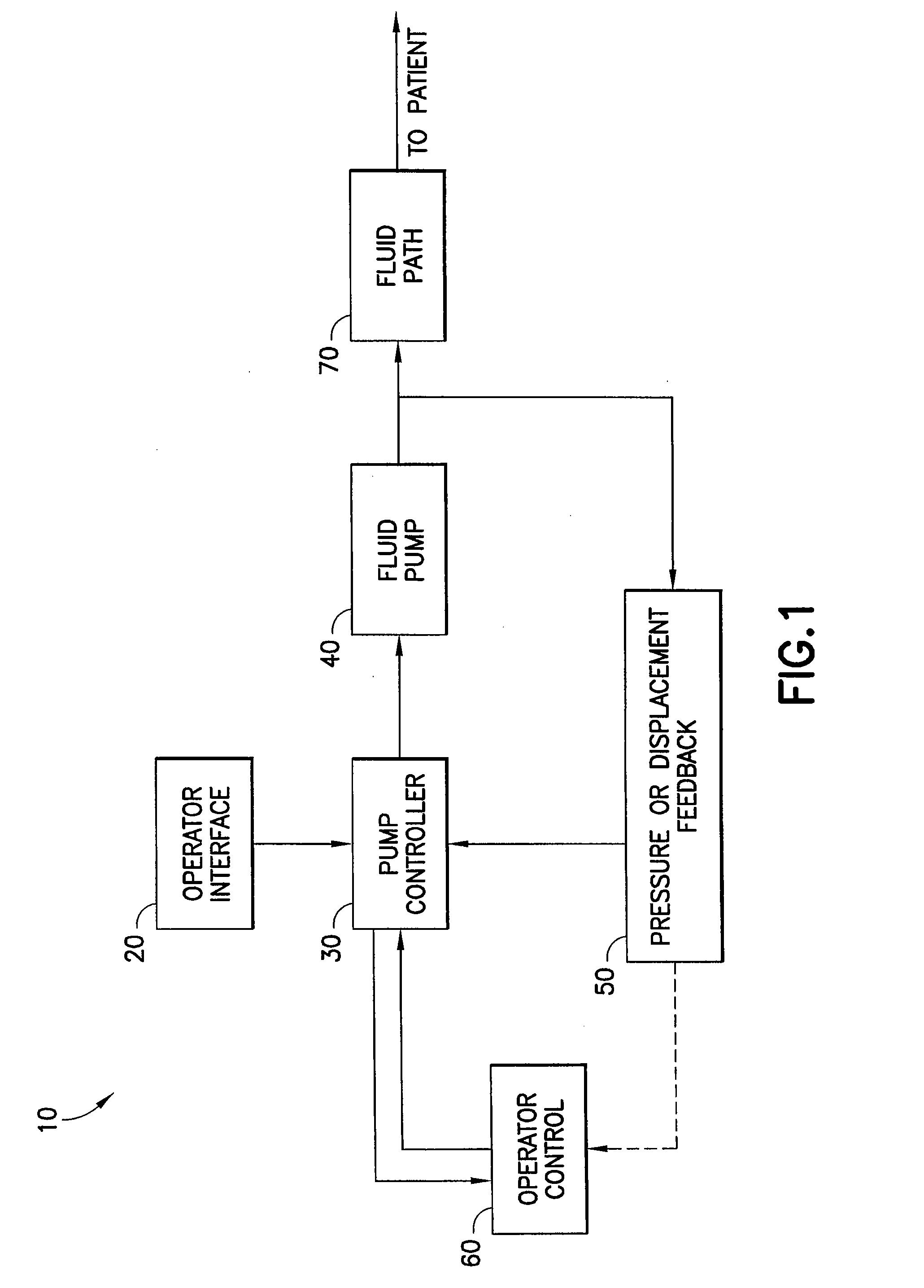
[0048]FIG. 1 is a block diagram showing the basic components of a fluid injection and inflation system 10 (hereinafter “system 10”) pursuant to an embodiment of the invention. Generally, system 10 includes a plurality of operatively connected components, comprising: (1) an operator interface 20; (2) a pump controller 30; (3) a fluid pump 40; (4) a fluid parameter feedback device 50; (5) an operator control 60; and (6) a fluid path...


PUM


Abstract

A combined fluid injection and inflation system is disclosed and includes a fluid delivery system including at least one pressurizing device, a fluid path, and a control unit. The fluid path is adapted to connect the pressurizing device to a patient via a catheter including a balloon and inserted in the patient. The control unit is operable to control the fluid delivery system. In operation, the control unit selectively actuates the fluid delivery system to operate in a fluid injection mode or in a balloon inflation mode. In the fluid injection mode the pressurizing device delivers fluid to the fluid path for a fluid injection procedure. In the balloon inflation mode, the pressurizing device delivers fluid to the fluid path for inflating the balloon associated with the catheter. An operator control may be connected to the control unit for controlling the fluid delivery system and may be a handheld device.

Description

CROSS REFERENCE TO RELATED APPLICATION [0001] This application claims priority to and benefit of U.S. Provisional Patent Application No. 60 / 692,517 filed Jun. 21, 2005, the disclosure of which is incorporated herein by reference in its entirety.BACKGROUND OF THE INVENTION [0002] 1. Field of the Invention [0003] This invention relates to a combined fluid injection and inflation system that may be used to assist with both the diagnostic and therapeutic portions of percutaneous transluminal angioplasty (PTA), (balloon inflation / deflation), and with angioplasty procedures in general. The combined injection and inflation system is used to inject fluids such as contrast media (“contrast”) for diagnostic imaging, catheter or guidewire placement, drug delivery or any similar fluid delivery application as well as to provide a balloon inflation capability for balloon angioplasty, balloon assisted stent deployment or other inflation applications. The system may be used with, but is not restric...

Claims


Application Information

Patent Timeline
Patent Type & Authority Applications(United States)
IPC IPC(8): A61M29/00A61F2/958A61M25/10
CPCA61M5/007A61M5/14566A61M5/16827A61M5/16854A61M2025/1022A61M25/1018A61M25/104A61M2025/102A61M25/007A61M25/10184
Inventor GRIFFITHS, DAVID M.ALMON-MARTIN, ROSEMARYHIRSCHMAN, ALAN D.REILLY, DAVID M.TROCKI, MARKTROMBLEY, FREDERICK W. IIIUBER, ARTHUR E. IIIWEICH, THOMAS R.JAECKLEIN, WILLIAM J.
Owner BAYER HEALTHCARE LLC
Why Eureka
Try Eureka