System For Monitoring Condition Of Wheel

Inactive Publication Date: 2007-08-23
AISIN SEIKI KK
View PDF4 Cites 6 Cited by
  • Summary
  • Abstract
  • Description
  • Claims
  • Application Information

AI Technical Summary

Benefits of technology

[0012] With such a configuration, if the wheel rotates, the transmitting antenna transmits a polarized wave that is in parallel with the rotational axis of the wheel independently of the rotation of the wheel, and the receiving antenna, which is sensitive to the polarized radio wave in parallel with the rotational axis of the wheel, receives the transmitted polarized wave. This is because the direction perpendicular to the direction of travel of the vehicle and in parallel with the ground coincides with the direction of the rotational axis. Settings of the receiving antenna associated with each wheel are determined so that it can work the same way as a dipole antenna that is om

Problems solved by technology

However, to increase the sensitivity of an antenna, the size of the antenna has to be undesirably increased.
Therefore, it is difficult to dispose the antenna at a preferred

Method used


Image

  • System For Monitoring Condition Of Wheel
  • System For Monitoring Condition Of Wheel
  • System For Monitoring Condition Of Wheel

Examples


second embodiment

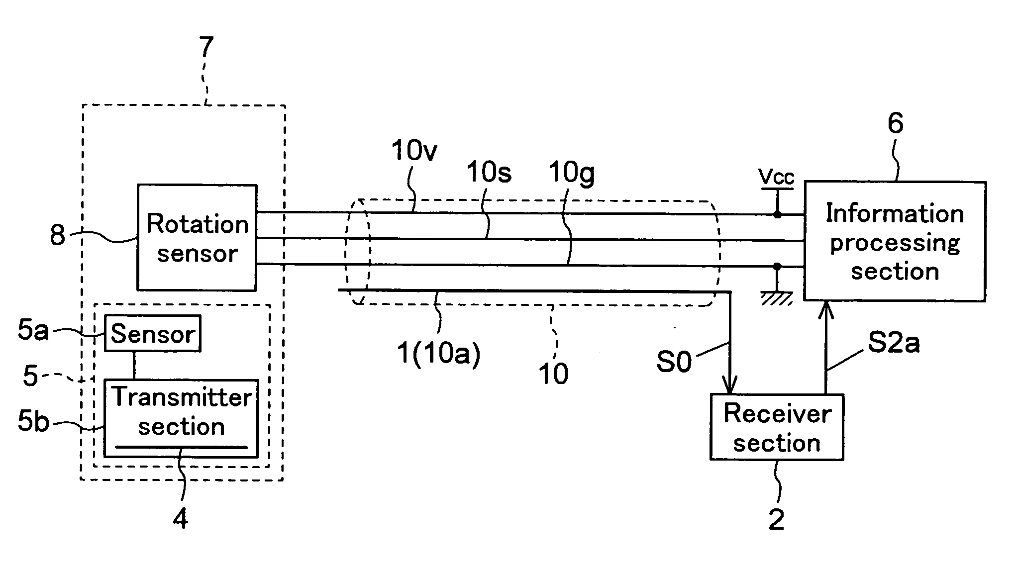
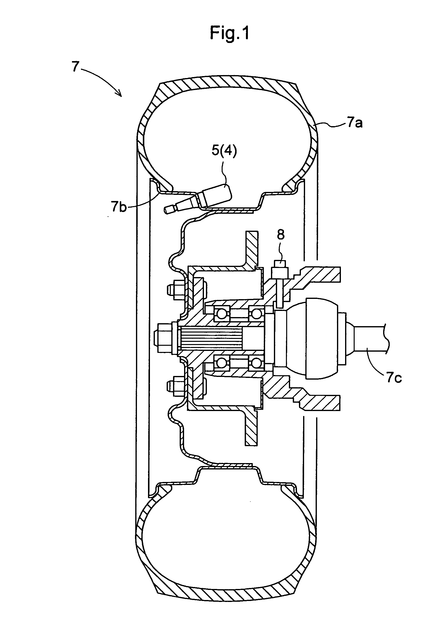
[0052] Now, a second embodiment will be described. A wheel unit 7 often has an external device for measuring the condition of a wheel, in addition to an air pressure monitor 5. For example, as shown in FIG. 1, a rotation sensor 8 that detects rotational conditions of the wheel unit 7, such as rotational speed and rotational direction, is provided in the vicinity of a drive shaft 7c that coincides with the rotational axis of a tire 7a.

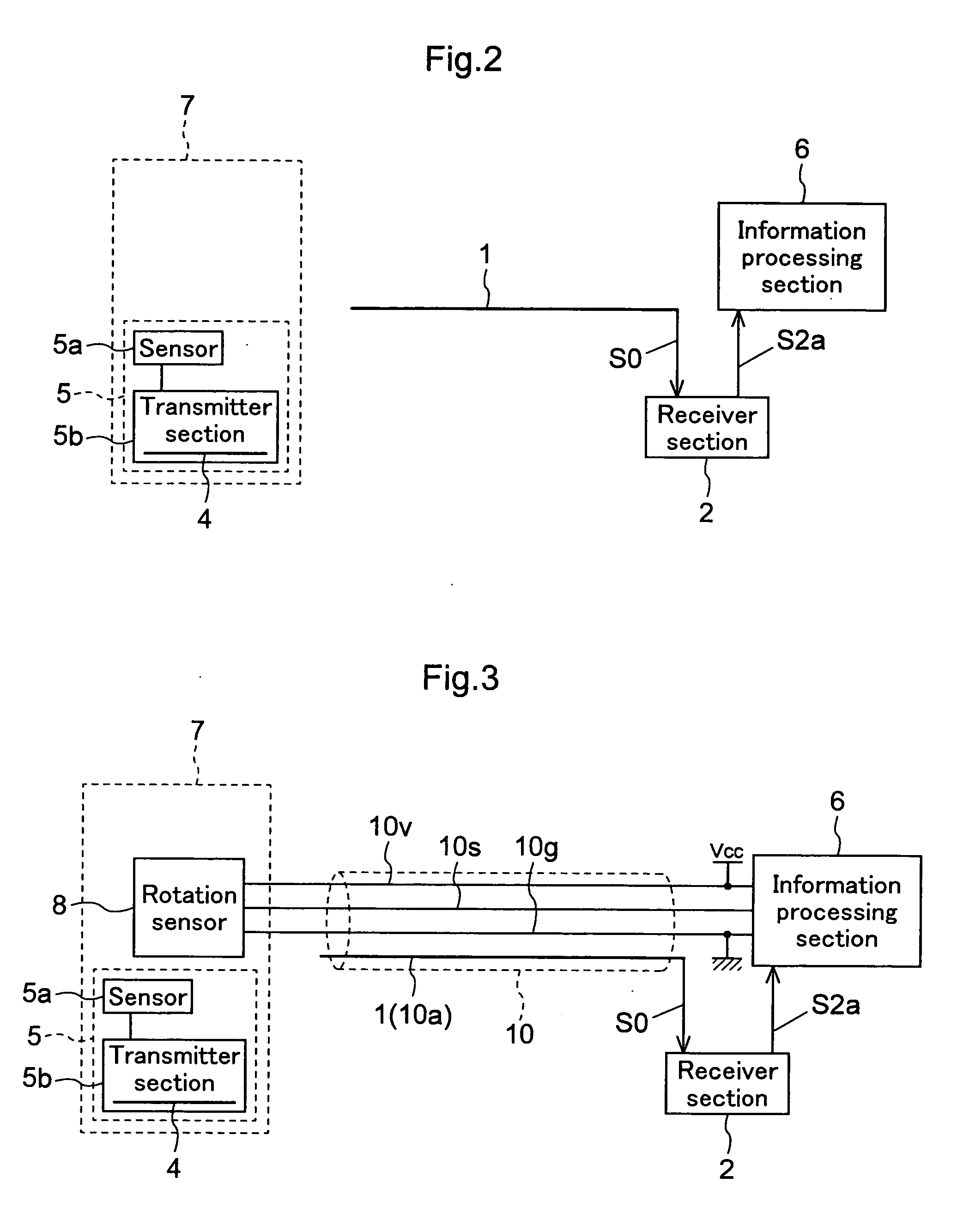
[0053] The measurement information (detection signal) obtained by the rotation sensor 8, which is an exemplary external device, is transmitted to an information processing section 6 via a signal wire 10s as shown in FIG. 3, for example. The rotation sensor 8 itself is fixed and does not rotate with the tire 7a and a wheel 7b. Therefore, even wiring can be provided along the drive shaft 7c that coincides with the rotational axis. In this embodiment, the wiring is composed of three wires including the signal wire 10s, a power supply wire 10v and a ground...

third embodiment

Modification 2 of Third Embodiment

[0070] Alternatively, as shown in FIGS. 7 and 8, a receiver section 2 may demodulate measurement information obtained by an air pressure monitor 5 and modulated by a transmitter section 5b, combine the demodulated measurement information with a measurement information signal S8 (detection signal) from a rotation sensor 8 to form a combined waveform S2b, and then transmit the combined signal to an information processing section 6. This will be described in detail below.

[0071] First, a receiver circuit 2a receives, amplifies and demodulates measurement information obtained by an air pressure monitor 5. Then, a signal processing circuit 2b combines the demodulated measurement information S1b obtained by the air pressure monitor 5 with a measurement information signal S8 (detection signal) from a rotation sensor 8. In the example shown in FIG. 8, pulses of the measurement information signal S8 (detection signal) from the rotation sensor 8, whose period...


PUM


Abstract

To provide a system for monitoring the condition of a wheel that has a high mountability and can adequately transmit and receive measurement information about a wheel using radio wave transmission. A system for monitoring the condition of a wheel 7 includes: a measurement section 5 that obtains measurement information about the wheel 7; and a transmitter section 5b that transmits by radio the measurement information obtained by the measurement section 5, which are located on the side of the wheel 7; and a receiver section 2 that receives the measurement information transmitted by radio from the transmitter section 5b; and an information processing section 6 that determines the condition of the wheel 7 based on the measurement information S2a received by the receiver section 2, which are located on the side of a vehicle body, in which a transmitting antenna 4 that transmits by radio the measurement information S0 using a polarized wave that is in parallel with the rotational axis of the wheel 7 is provided on the side of the wheel 7, and a receiving antenna 1 sensitive to a polarized radio wave that is perpendicular to the direction of travel of the vehicle and in parallel with the ground is provided on the side of the vehicle body.

Description

TECHNICAL FIELD [0001] The present invention relates to a system for monitoring the condition of a wheel, the system comprises a measurement section that obtains measurement information about a wheel and a transmitter section that transmits by radio the measurement information obtained by the measurement section, both of which are located on the side of the wheel, and a receiver section that receives the measurement information transmitted by radio from the transmitter section and an information processing section that determines the condition of the wheel based on the measurement information received by the receiver section, both of which are located on the side of a vehicle body. BACKGROUND ART [0002] In a system in which the condition of an external device outside a vehicle body, such as the air pressure of a tire, is measured, and the measurement result is transmitted by radio to an information processing device that uses the measurement result inside the vehicle body, a weak ra...

Claims


Application Information

Patent Timeline
IPC IPC(8): G05D1/00G08C17/02B60C23/02B60C23/04B60C23/20
CPCB60C23/0444B60C23/0408
Inventor KATO, MANABUFUJIOKA, EIJI
Owner AISIN SEIKI KK
Why Eureka
Try Eureka