Data correction apparatus, data correction method, magnetic resonance imaging apparatus and X-ray CT apparatus

a data correction and data technology, applied in the field of data correction apparatus, data correction method, magnetic resonance imaging apparatus and x-ray ct (computed tomography) apparatus, can solve the problems of non-uniformity of image data, nmr signal, signal intensities, etc., and achieve the non-uniformity of wb coil sensitivity at an ignorable level

Inactive Publication Date: 2007-08-23
TOSHIBA MEDICAL SYST CORP
View PDF0 Cites 40 Cited by
  • Summary
  • Abstract
  • Description
  • Claims
  • Application Information

AI Technical Summary

Benefits of technology

[0018]The data correction apparatus, the data correction method, the magnetic resonance imaging apparatus and the X-ray CT apparatus as described above make it possible to obtain uniform data by correcting a spatially nonuniform sensitivity distribution of a sensor with simply processing with keeping spatial uniformity of an SNR distribution.

Problems solved by technology

However, when the RF coil is structured of the phased-array coil and the WB coil, signal intensities of the image data obtained through a reconstruction processing together with the NMR signals have also nonuniformity depending on the nonuniformity of the sensitivity of the phased-array coil or the WB coil.
In general, the nonuniformity of the sensitivity of the WB coil is sufficiently small at an ignorable level.
However, in particular, the nonuniformity of the sensitivity of each surface coil in the phased-array coil used for each purpose is large and affects the image data.
However, in the MR imaging while using the above-mentioned plural surface coils and the MR imaging while using the single surface coil, when the sensitivity distribution of the surface coil is corrected, there is a problem in that a spatial nonuniformity occurs in the SNR.
Therefore, if the sensitivity distribution of the surface coil is corrected and the signal intensity of the image data depending on the space is set constant, the image noise becomes spatially nonuniform.
As a result, the SNR becomes spatially nonuniform, which leads to the degradation in the image quality, and thus the spatial nonuniformity of the SNR is not preferable in the diagnosis.
In addition, in a medical device such as other image diagnostic apparatus or a biological information measuring instrument other than the MRI apparatus using the surface coils as the sensors as well, if the intensities of the signals obtained while the spatially nonuniform sensitivity distribution of the sensor is collected are set constant, the spatial nonuniformity occurs in the SNR together with the noise, which may lead to the degradation in the quality of image or the measurement result.

Method used


Image

  • Data correction apparatus, data correction method, magnetic resonance imaging apparatus and X-ray CT apparatus
  • Data correction apparatus, data correction method, magnetic resonance imaging apparatus and X-ray CT apparatus
  • Data correction apparatus, data correction method, magnetic resonance imaging apparatus and X-ray CT apparatus

Examples


first embodiment

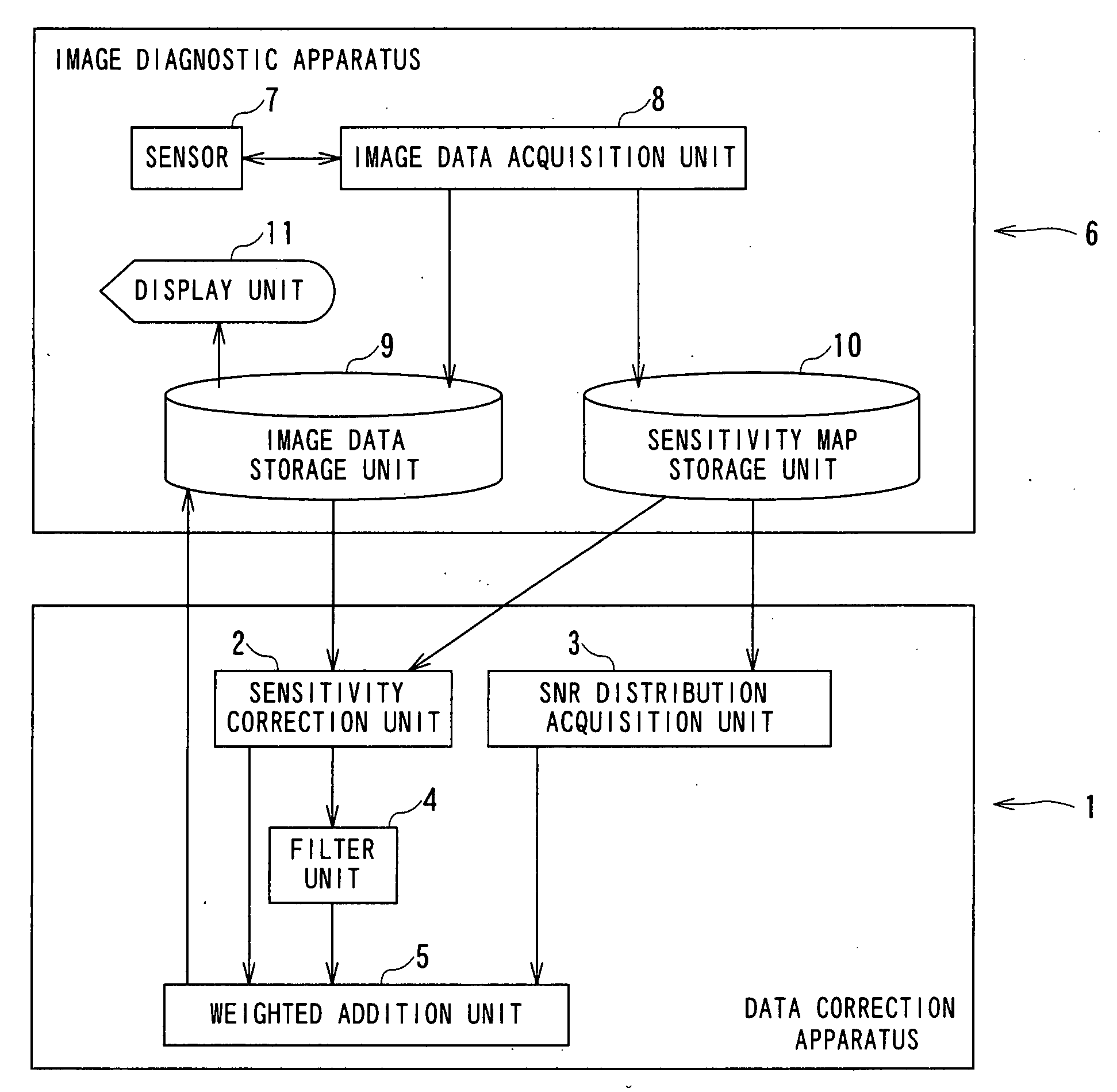
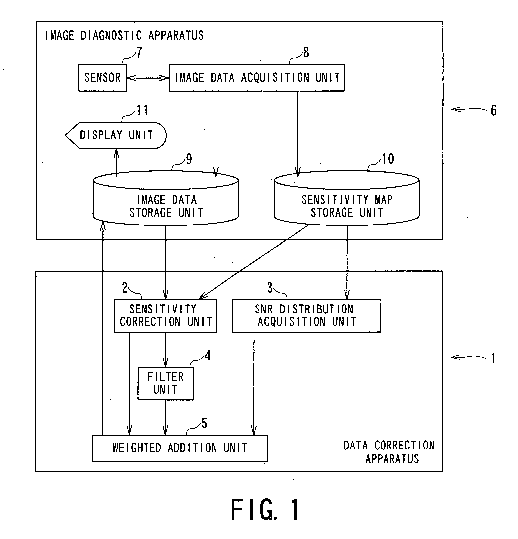
[0050]FIG. 1 is a functional block diagram showing a data correction apparatus according to the present invention.

[0051]A data correction apparatus 1 is structured by a computer reading a program. It should be noted that an entirety or a part of the data correction apparatus 1 may be structured by a circuit. The data correction apparatus 1 includes a sensitivity correction unit 2, an SNR distribution acquisition unit 3, a filter unit 4 and weighted addition unit 5. Thus, these elements give, to the data correction apparatus 1, a function to acquire uniform data by performing correction processing of a spatially nonuniform sensitivity distribution of a sensor with keeping spatial uniformity of an SNR distribution to data acquired by a medical apparatus like an image diagnostic apparatus and a measuring device for living body information.

[0052]Examples of a medical apparatus for collecting the data that is the correction target includes a biological information measuring instrument su...

second embodiment

[0105]FIG. 3 is a functional block diagram showing a data correction apparatus according to the present invention.

[0106]In the data correction apparatus 1A shown in FIG. 3, constructions including a data dividing unit 12 and an addition unit 13 instead of the weighted addition unit 5 are different from those of the data correction apparatus 1 shown in FIG. 1. Other constructions and operations of the data correction apparatus 1A are not different from those of the data correction apparatus 1 shown in FIG. 1 substantially. Therefore, same number is attached to a same component as that of the data correction apparatus 1 and explanation thereof is omitted.

[0107]Specifically, the data correction apparatus 1A includes a data dividing unit 12 and an addition unit 13 in addition to the sensitivity correction unit 2, the SNR distribution acquisition unit 3 and the filter unit 4. Then, the sensitivity correction unit 2 is configured to supply the sensitivity correction image data to the data...

third embodiment

[0128]FIG. 5 is a functional block diagram showing a data correction apparatus according to the present invention.

[0129]In the data correction apparatus 1B shown in FIG. 5, an order of processing is different from that of the data correction apparatus 1 shown in FIG. 1. Other constructions and operations of the data correction apparatus 1B are not different from those of the data correction apparatus 1 shown in FIG. 1 substantially. Therefore, same number is attached to a same component as that of the data correction apparatus 1 and explanation thereof is omitted.

[0130]The data correction apparatus 1B is provided with the sensitivity correction unit 2, the SNR distribution acquisition unit 3, the filter unit 4, and the weighted addition unit 5.

[0131]The filter unit 4 has a function of acquiring the original image data that is the target of the sensitivity correction from the image data storage unit 9, a function of performing the filter processing with use of the uniform filter on t...


PUM

PropertyMeasurementUnit
weightsaaaaaaaaaa
magneticaaaaaaaaaa
magnetic resonance imageaaaaaaaaaa

Abstract

A data correction apparatus includes a sensitivity correction unit and an SNR distribution correcting unit. The sensitivity correction unit produces first processed data by performing sensitivity correction to first objective data obtained based on correction objective data using ununiform sensitivity distribution of a sensor for acquiring the correction objective data. The SNR distribution correcting unit produces pieces of component data each subjected to corresponding weighting depending on an SNR distribution and corresponding filtering having a mutually different intensity using second objective data obtained based on the correction objective data to produce second processed data by compounding the pieces of the component data.

Description

BACKGROUND OF THE INVENTION[0001]1. Field of the Invention[0002]The present invention relates to a data correction apparatus, a data correction method, a magnetic resonance imaging apparatus and an X-ray CT (computed tomography) apparatus which correct data showing a spatially nonuniform SNR (signal to noise ratio) distribution due to a sensor's sensitivity showing a spatial distribution so that the corrected data are uniform.[0003]2. Description of the Related Art[0004]A MRI (Magnetic Resonance Imaging) apparatus is conventionally used as a monitoring apparatus in a medical field (see, for example, Japanese Patent No. 3,135,592).[0005]The MRI apparatus is an apparatus which generates gradient magnetic fields by gradient coils on an imaging area of an object set in a cylindrical static field magnet for producing a static magnetic field, resonates nuclear spins in the object magnetically by transmitting RF (Radio Frequency) signals from an RF coil and reconstructs an image of the obj...

Claims


Application Information

Patent Timeline
Patent Type & Authority Applications(United States)
IPC IPC(8): G06F19/00A61B5/055A61B6/03A61B8/00G01R33/34G01R33/54G06V10/30
CPCA61B6/032G06T5/002A61B6/585C12N15/111C12N2310/14C12N2310/315C12N2310/32C12N2310/321C12N2310/3231C12N2310/341C12N2310/346C12N2320/51G01R33/3415G01R33/56G01R33/5608G01R33/5611G06K9/40G06T2207/10072G06T2207/30004A61B6/5205C12N2310/3521G06V10/30
Inventor KIMURA, TOKUNORI
Owner TOSHIBA MEDICAL SYST CORP
Why Eureka
Try Eureka