Gear alignment and slip assembly for drive transmission system of multi-faced signs and billboards

a transmission system and multi-faced technology, applied in the field of mechanical advertising displays, can solve the problems of high cost, high cost, and difficulty in reliability and maintenance, and achieve the effect of strong and durabl

Inactive Publication Date: 2007-08-30
ACTION GRAPHIX
View PDF20 Cites 14 Cited by
  • Summary
  • Abstract
  • Description
  • Claims
  • Application Information

AI Technical Summary

Benefits of technology

[0025]According to a second aspect of the invention, the sign includes a slip subassembly operatively associated between the drive shaft and the output shaft. The slip subassembly comprises: (i) an input slip element: (a) operatively connected to be rotated by the drive shaft; (b) defining an input slip rotational axis; (c) defining a generally arcuate line that has a radius from the input slip rotational axis at least as large as the radius of the plurality of input gear teeth, that is non-intersecting with the input slip rotational axis, and that extends around a first portion of the input slip rotational axis, and (d) defining a generally arcuate gap along an arcuate line that has a radius from the input slip rotational axis at least as large as the radius of the plurality of input gear teeth, and that extends around a second portion of the input slip rotational axis; and (ii) an output slip element: (a) operatively connected to the output shaft; (b) defining an output slip rotational axis; and (c) defining a generally straight line that has a radial distance from the rotational axis of the output slip hub at least as large as the radius of the plurality of output gear teeth, that is non-intersecting with the input slip rotational axis, and that extends perpendicular to the input rotational axis of the input slip, the straight line adapted to be rotationally positioned into substantially co-planar alignment with the generally arcuate line defined by the input slip element. During a first portion of a 360 degree axial rotation of the input slip element, the arcuate line defined by the input slip element and the straight line defined by the output slip element are in substantially co-planar alignment, and the input and output slip elements are in slipping contact as the input slip element rotates to prevent the output slip element from rotating. During a second portion of a 360 degree rotation of the input slip element, the arcuate line defined by the input slip element and the straight line defined by the output slip element are out of co-planar alignment as the input slip element rotates, and the elements are out of slipping contact to allow the output slip element to rotate. It is believed that the large radius of the slip subassembly provides mechanical advantage and is stronger and more durable.

Problems solved by technology

Typical mechanical signs, however, have experienced many problems.
For example, the synchronization of the louvers must be maintained, or the displays will be disrupted.
The mechanical interlocking of the louvers has posed reliability and maintenance difficulties and high costs.
The larger the size of the sign magnifies these problems.
Over the years, many designs have been tried to improve the reliability and reduce maintenance costs associated with this kind of sign, however, problems with reliability and maintenance have continued to plague the industry.
But the highly complex inter-workings to regulate the turning of particular triangle portions of each indicator and the many moving parts increased the possibility of breakdown and the difficulty of repair.
While several of the prior patents, including U.S. Pat. Nos. 5,161,421; 6,128,841; and 6,295,882 describe certain useful design elements, the prior art still does not adequately solve the problem.
For example, while the knobbed cam driver disclosed in U.S. Pat. No. 6,128,841 is interesting, it is not equivalent to the efficiency and reliability of a geared system.

Method used


Image

  • Gear alignment and slip assembly for drive transmission system of multi-faced signs and billboards
  • Gear alignment and slip assembly for drive transmission system of multi-faced signs and billboards
  • Gear alignment and slip assembly for drive transmission system of multi-faced signs and billboards

Examples


Embodiment Construction

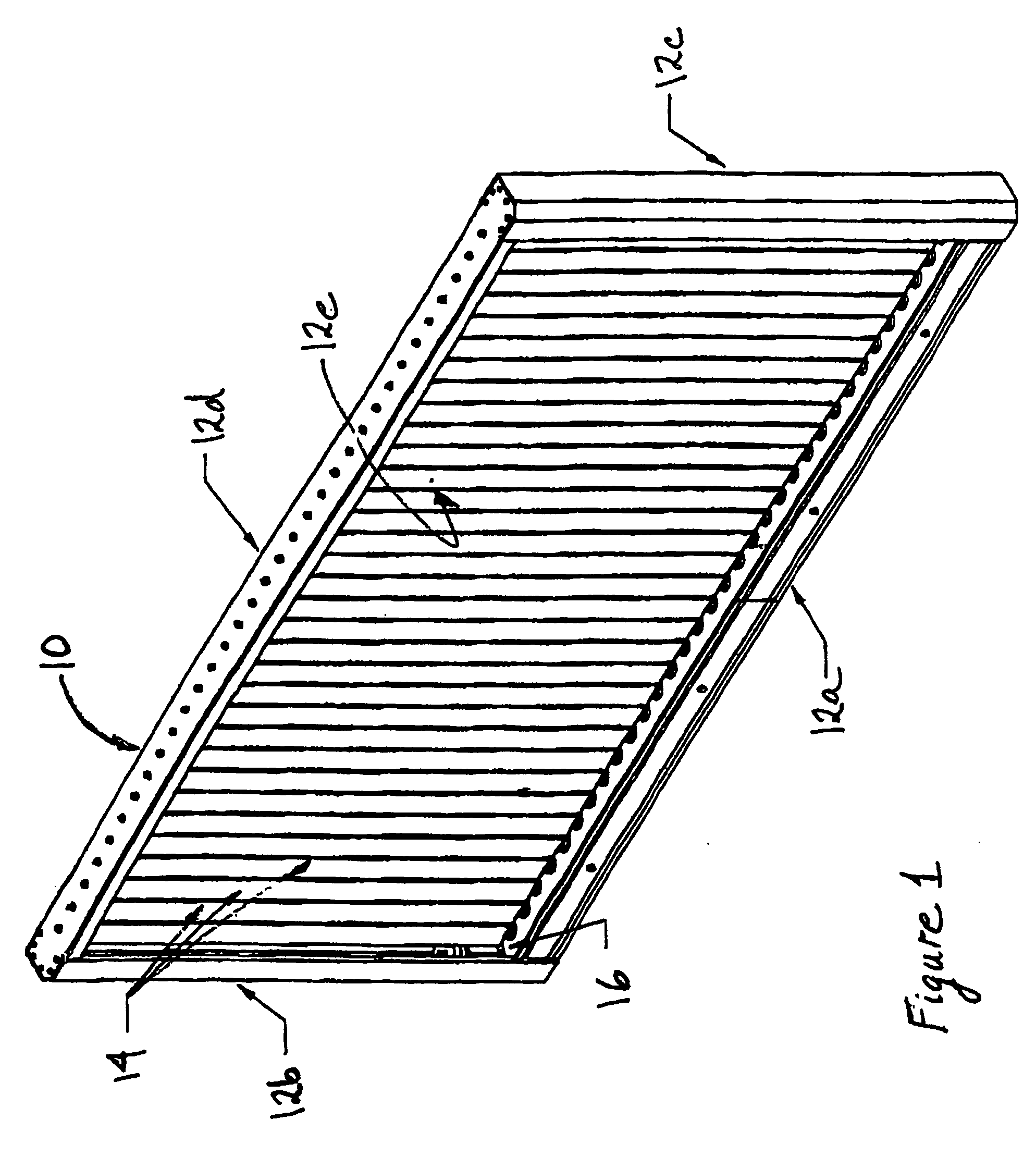
[0042]As used herein, the word “billboard” refers to a large sign, typically a large format sign for outdoors. The preferred embodiments of various aspects of this invention are particularly adapted to be able to be used in “large format” outdoor billboard displays. For example, our present expectation is that this design will work well in a large format sign up to a typical size used in the United States of fourteen (14) feet tall and forty-eight (48) feet long, and preferably in a sign substantially larger than that.

[0043]It is to be understood that, unless expressly noted, relational terms such as “vertical”, “horizontal”, “bottom”, “top”, “lower”, “upper”, “front”, “back”, “side”, “left”, “right”, “clockwise”, “counter-clockwise”, etc. are arbitrarily assigned for convenient reference to the orientation and perspective of the figures of the drawing. Furthermore, it is to be understood that relative terms such as “length”, “width”, “height”, etc. are also arbitrarily assigned for...


PUM


Abstract

A sign (10) includes a gear subassembly (50, 52) and a slip assembly (74, 80) operatively associated between the drive shaft (42) and the output shaft (46) of one of the display elements (14). During a portion of a rotation of the input gear element (50), the input gear teeth (72) engage the output gear teeth (78). During another portion, the input gear teeth (72) disengage. At least one partial gear tooth (82a, 82b) assists in periodically aligning the gear teeth. The slip subassembly comprises: an input slip element (74) defining a generally arcuate line about the axis of the input slip element; and an output slip element (80) defining a generally straight line that is non-intersecting with and extends perpendicular to the input slip axis. During a portion of a rotation of the input slip element (74), the arcuate line and the straight line of the slip elements (74, 80) are in slipping contact to prevent the output slip element (80) from rotating. During another portion of the rotation, the output slip (80) can be rotated. The slip subassembly has a radius at least a large as the radius of the gear teeth (72, 78).

Description

CROSS REFERENCE TO RELATED APPLICATIONS[0001]This application claims the priority of PCT patent application Serial No. PCT / US04 / 28898, filed Sep. 5, 2003, which claimed the priority of U.S. patent application Ser. No. 60 / 500,411, filed Sep. 5, 2003, now abandoned.TECHNICAL FIELD[0002]The present invention relates to mechanical advertising displays, and more particularly, to signs and billboards that use multi-faced louvers to enable multiple sign displays, usually three, to be periodically or selectively shown on a single structure.BACKGROUND[0003]Advertising signs are a widely used means of passing on advertising messages to the general public. Of particular success are sign displays that use a plurality of sign elements in the general shape of triangular prisms to enable three billboard type displays to be periodically or sequentially shown on a single structure.[0004]The triangular prism segments, referred to in the art by various names such as “display elements” or “louvers”, ar...

Claims


Application Information

Patent Timeline
Patent Type & Authority Applications(United States)
IPC IPC(8): G09F11/02
CPCG09F11/025
Inventor ATKINSON, MICHAEL R.
Owner ACTION GRAPHIX
Why Eureka
Try Eureka