
Band saw blade

a technology of band saw blades and blades, which is applied in the direction of saw blades, saw chains, manufacturing tools, etc., can solve the problems of blade breakage, blade replacement, loss of efficiency, etc., and achieve the effect of improving the efficiency and performance of blades

Inactive Publication Date: 2007-08-30
COOKS SAW MFG
View PDF26 Cites 40 Cited by
  • Summary
  • Abstract
  • Description
  • Claims
  • Application Information

AI Technical Summary

Benefits of technology

[0013] Generally, the present invention provides a band saw blade with a novel geometrical structure for improving the efficiency and performance of a blade.

Problems solved by technology

Generally, a band saw blade is replaced because of tooth wear, stress or some other performance limiting problem.
A worn blade, such as a blade with worn teeth, causes an undesirable loss in efficiency that may cause the blade to break due to increased stress.
In addition, a worn blade may cause damage to the band saw body that is pulling the blade.
A worn blade also increases power requirements thereby increasing the energy expense of the sawing operation.
In general, a sawmill using a band saw regards downtime as undesirable since there is a cost associated with non-productive use of the saw.

Method used


Image

  • Band saw blade
  • Band saw blade
  • Band saw blade

Examples


Embodiment Construction

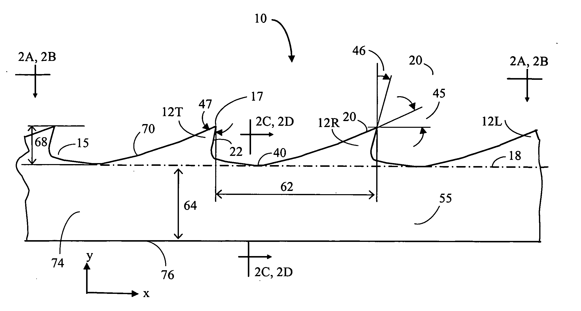
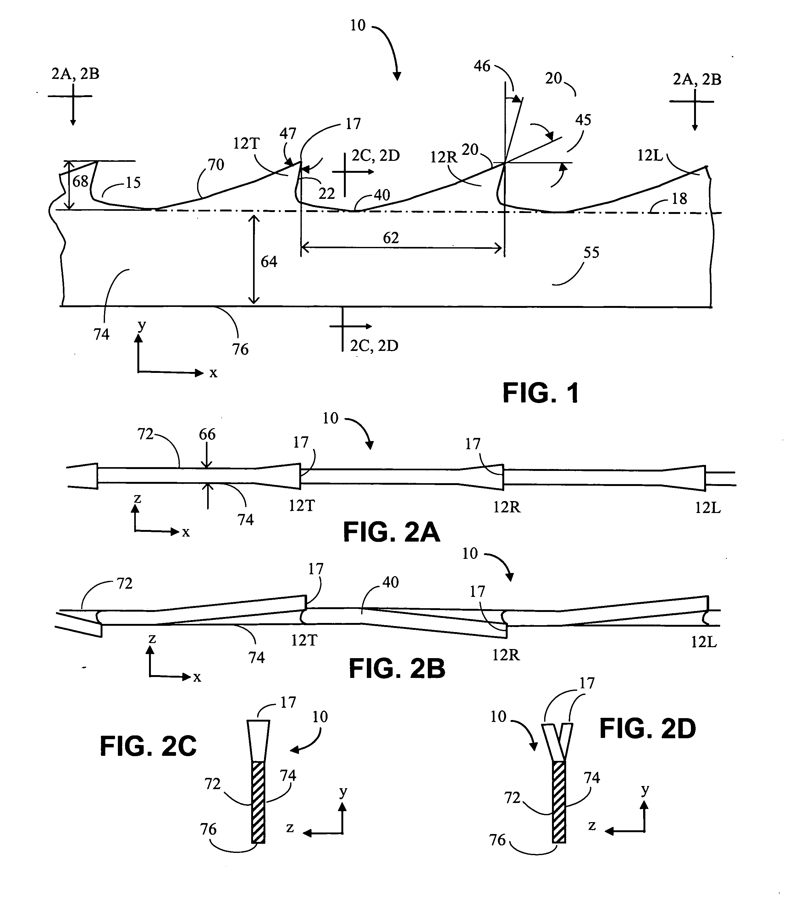
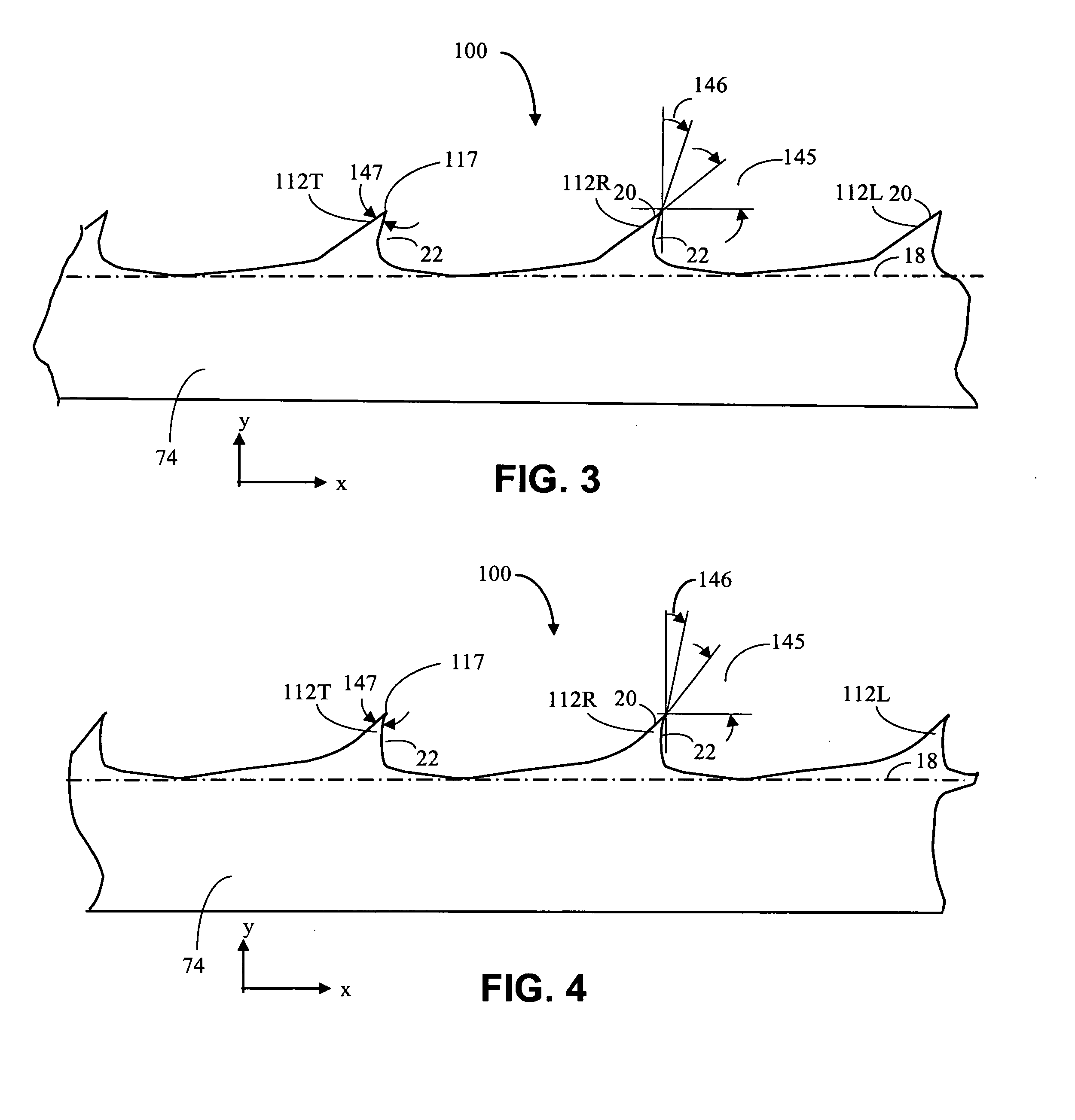
[0024] The present invention generally pertains to band saw blades and the geometrical structure of such blades. A brief description of blade geometry is. provided for a conventional blade and is further used to define terms suitable for describing embodiments the band saw blade of the present disclosure.

[0025] Referring to FIG. 1 there is shown a conventional blade 10 having teeth 12 that remove material from a work piece (not shown), such as, for example a log or other piece of wood. The blade 10 moves in the x direction and the work piece moves in the negative y direction. A reference tooth 12R is adjacent to a leading tooth 12L, located in the x direction from the reference tooth 12R. The leading tooth 12L removes some material from the work piece before the reference tooth 12R makes contact with the work piece. A trailing tooth 12T, also adjacent to the reference tooth 12R and located in the negative x direction from the reference tooth 12R, makes contact with the work piece s...


PUM

PropertyMeasurementUnit
back angleaaaaaaaaaa
hook angleaaaaaaaaaa
back angleaaaaaaaaaa

Abstract

The invention relates to the structure of a band saw blade. The band saw blade has teeth with an improved geometrical shape that increases the efficiency of the blade. The tooth shape of a band saw blade is defined in part by the back angle and the hook angle, wherein the back angle of the disclosed embodiment exceeds the value of back angle of conventional band saw blades.

Description

CROSS-REFERENCE TO RELATED APPLICATIONS [0001] This application is related to Cook, U.S. Provisional Patent Application No. 60 / 776,634, entitled “Band Saw Blade” filed on Feb. 25, 2006 and is incorporated by reference herein, with priority claimed for all commonly disclosed subject matter.FIELD OF THE INVENTION [0002] The present invention generally relates to the field of band saw blades for cutting wood and other materials. RELATED ART [0003] The teeth of a band saw blade work as tiny planing tools that generate chips at a high speed by planing and / or tearing, the chips being collected and removed in the tooth gullets. The development of increasingly efficient band saws has aimed at further developing this planing and / or tearing function of band saw blades. It is a typical feature of band saw blades that the teeth are set, swaged or otherwise configured so as to provide a kerf (a space generated by the cutting) that is somewhat greater than the blade thickness, for example, twice ...

Claims


Application Information

Patent Timeline
Patent Type & Authority Applications(United States)
IPC IPC(8): B26D1/46
CPCB27B33/02B23D61/121Y10T83/04Y10T83/9317
Inventor COOK, JAMES TIMOTHYCOOK, STEPHEN OTHNIEL
Owner COOKS SAW MFG
Learn More