Sheet cutting device, printer, and sheet cutting method

a cutting device and printer technology, applied in metal working devices, printing, other printing devices, etc., can solve the problems of reduced cutting performance, increased manufacturing costs, and reduced durability of fixed blades and movable blades, so as to reduce manufacturing costs, reduce manufacturing costs, and increase cutting performance. the effect of durability

Inactive Publication Date: 2007-08-30
SEIKO INSTR INC
View PDF28 Cites 15 Cited by
  • Summary
  • Abstract
  • Description
  • Claims
  • Application Information

AI Technical Summary

Benefits of technology

[0019] It is therefore an object of the present invention to provide a sheet cutting device capable of suppressing wear of blade edges of a fixed blade and a movable blade, increasing durability of cutting performance of the blade edges of the fixed blade and the movable blade, downsizing the device as a whole, and reducing manufacture costs, a printer, and a sheet cutting method.
[0021] According to the sheet cutting device of the present invention structured as described above, when cutting the sheet material, the blade edge of the fixed blade and the blade edge of the movable blade intersect with each other in a non-contact state, and the sheet material is cut by the blade edges. That is, the blade edge of the fixed blade and the blade edge of the movable blade do not come into contact with each other, so wear of the blade edges are suppressed, thereby increasing durability of cutting performance.
[0022] Further, according to the sheet cutting device, the cutting is performed while the blade edge of the fixed blade and the blade edge of the movable blade do not come into contact with each other, thereby reducing a load generated when cutting the sheet material. Therefore, it is possible to downsize the drive means, which reduces manufacture costs.
[0023] Further, according to the sheet cutting device, the wear of the blade edges of the fixed blade and the movable blade is suppressed, thereby reducing the load generated when cutting the sheet material. Accordingly, it is possible to use the fixed blade and the movable blade with the blade edges of those being flat. Thus, it is not required to use a special component or to apply an additional finish to the blade edges, thereby reducing manufacture costs of the fixed blade and the movable blade.
[0026] Further, one of the fixed blade and the movable blade, provided to the sheet cutting device according to the present invention, preferably has an introduction portion for guiding the blade edge of one of the fixed blade and the movable blade in the thickness direction of the other of those. With this construction, the introduction portion provided to one of the fixed blade and the movable blade is brought into sliding contact with the other of those, thereby, when the blade edge of the fixed blade and the blade edge of the movable blade intersect with each other, making it possible to guide a position in the thickness direction of the one blade edge in the thickness direction of the other blade edge.
[0029] As described above, according to the present invention, the wear of the blade edges of the fixed blade and the movable blade is suppressed, so it is possible to increase the durability of cutting performance of the fixed blade and the movable blade, to downsize the device as a whole, and to reduce the manufacture costs. Further, according to the present invention, the sheet material is cut by the flat fixed blade and the flat movable blade, so it is possible to form the cut section of the sheet material in a straight line.

Problems solved by technology

Thus, since the blade edges of the fixed blade and the movable blade come into sliding contact with each other, the conventional sheet cutting device wears easily, leading to a reduction in cutting performance, that is, poor durability.
Therefore, with the conventional cutting device, there is a problem in which cost of the forming material for the fixed blade and the movable blade and manufacture costs involved in additional processes increase.
Thus, in the conventional sheet cutting device, there is a disadvantage in which, for example, the actuator becomes larger, involving increase in costs of the actuator itself, thereby leading to an increase in size of the device as a whole.
Thus, in the conventional sheet cutting device, shapes of the fixed blade and the movable blade are complicated.
Therefore, it is required to perform dimensional control to form the blades into the shapes, leading to an increase in manufacture costs.
By curving one of the fixed blade and the movable blade in the thickness direction, there is a problem in that a cut portion of the sheet material does not constitute a straight line.

Method used


Image

  • Sheet cutting device, printer, and sheet cutting method
  • Sheet cutting device, printer, and sheet cutting method
  • Sheet cutting device, printer, and sheet cutting method

Examples


first embodiment

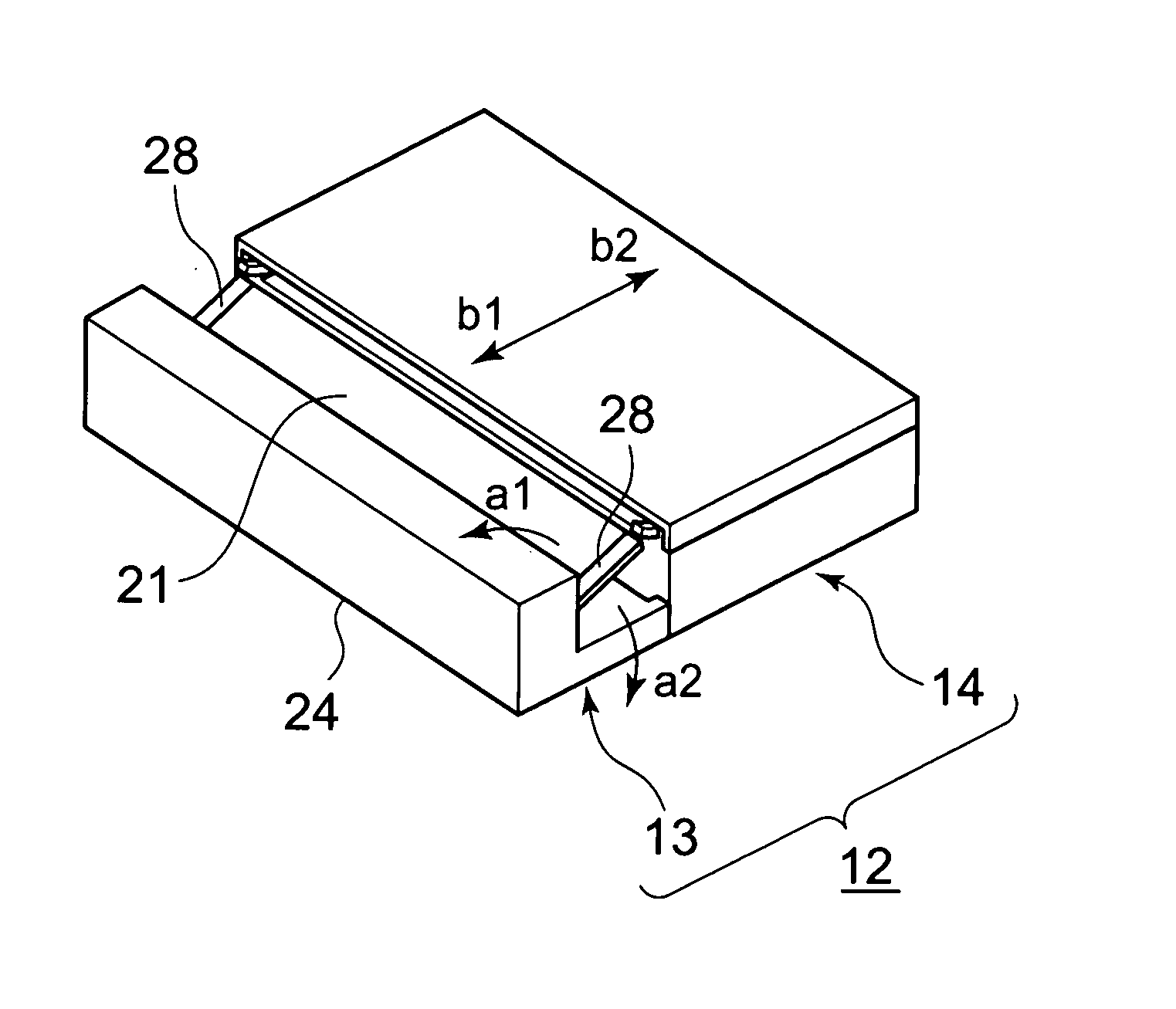
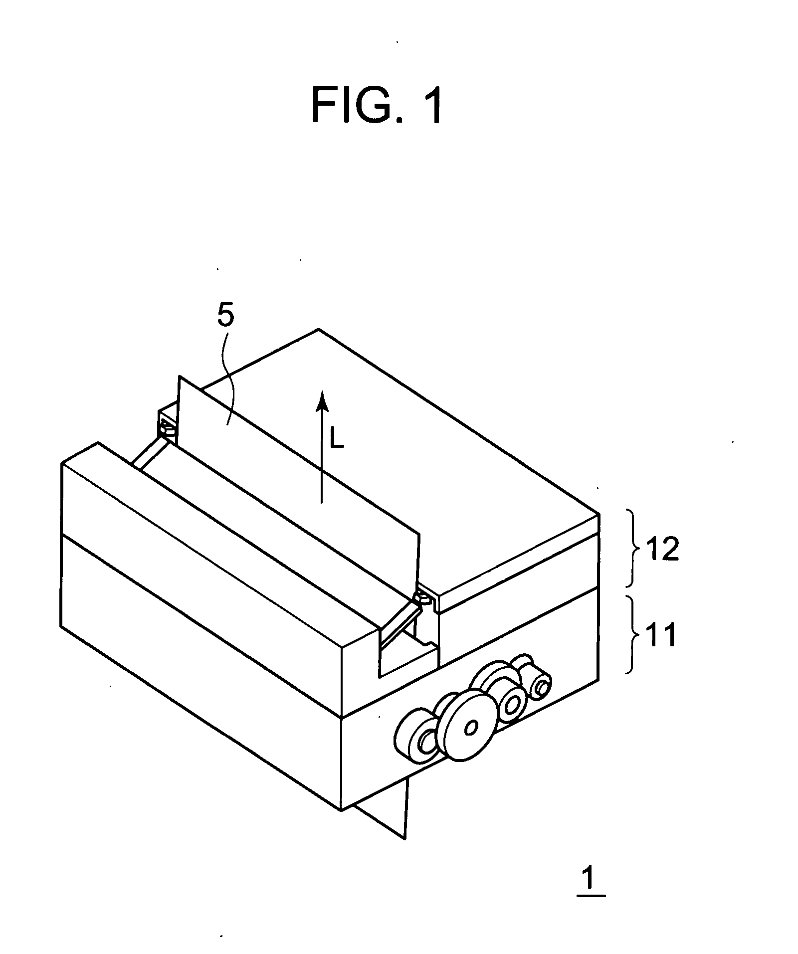
[0046] As shown in FIG. 1, a printer 1 includes a printing device 11 for performing printing on a sheet material 5 and conveying the sheet material 5, and a sheet cutting device 12 for cutting the sheet material 5 on which printing is performed by the printing device 11.

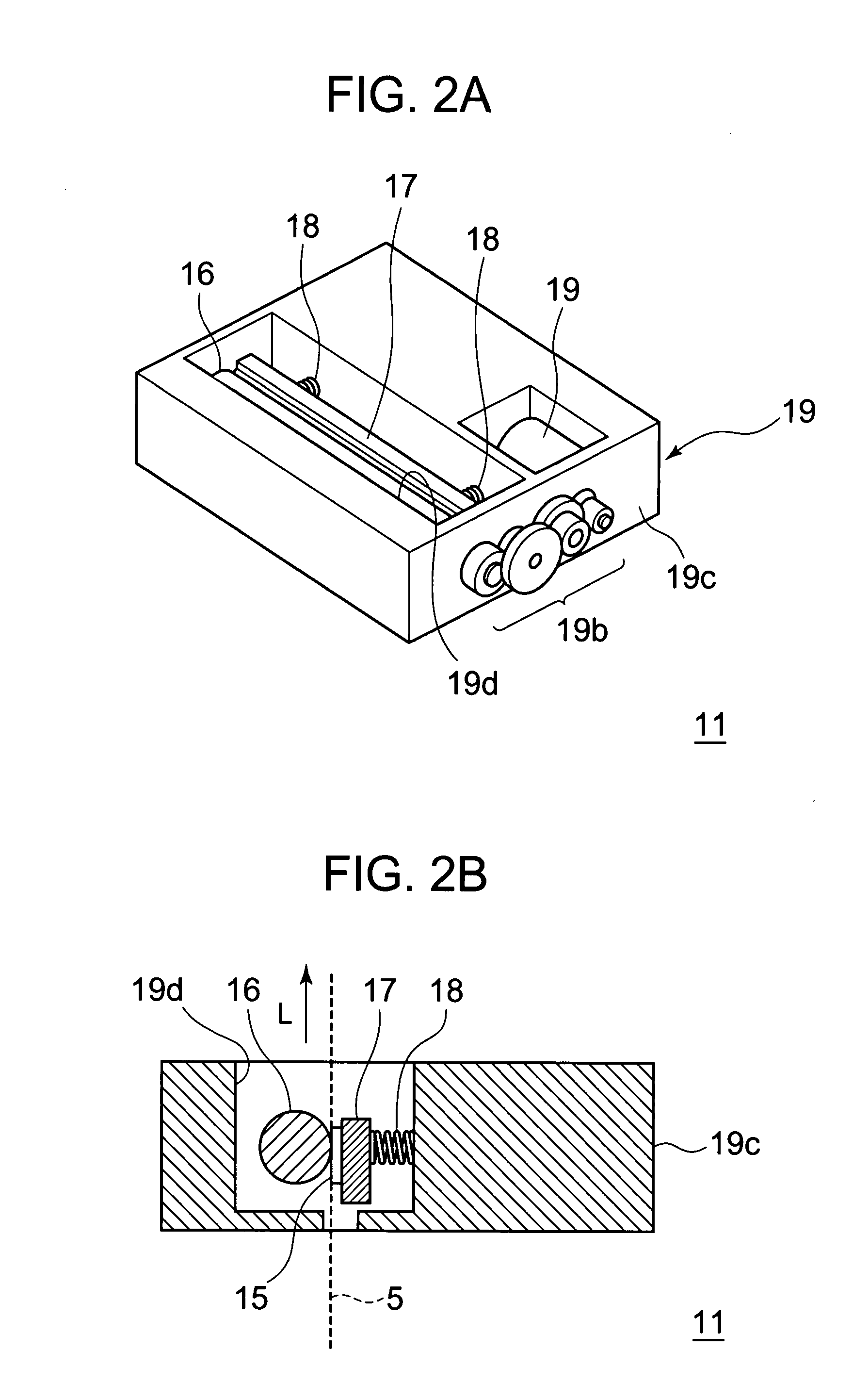
[0047] As shown in FIGS. 2A and 2B, for the printing device 11, a so-called thermal printer is used, and the printing device 11 includes thermal head 15 for allowing a heat sensitive print layer of the sheet material 5 to sense heat, a platen roller 16 brought into press contact with the thermal head 15, a head support body 17 for supporting the thermal head 15, a compression coil spring 18 for pressing the head support body 17 to the platen roller 16, and a drive mechanism 19 for rotating the platen roller 16.

[0048] The drive mechanism 19 includes a drive motor 19a, a gear train 19b for transmitting a driving force caused by the drive motor 19a to the platen roller 16, and a support block 19c for supporting the dr...

second embodiment

[0079] There will be described a second embodiment of the present invention in which spacers are provided on the movable blade 22 side unlike in the first embodiment adopting the structure in which the spacers 28 are provided on the fixed blade 21 side of the sheet cutting device 12. In the second embodiment, components identical to those of the above-mentioned first embodiment are denoted by the identical reference symbols and the description thereof will be omitted.

[0080] As shown in a portion B in each of FIGS. 8A and 8B, in the second embodiment, on the introduction portions 29 formed on the movable blade 22 provided to the sheet cutting device, spacers 38 to be brought into sliding contact with an opposing surface of the fixed blade 21 is provided.

[0081] Similarly to the spacers 28, the spacers 38 are formed so as to ensure the gap t equal to or smaller than a half of the thickness of the sheet material 5, and are joined to the introduction portions 29 of the movable blade 22...


PUM

PropertyMeasurementUnit
thicknessaaaaaaaaaa
thicknessaaaaaaaaaa
thicknessaaaaaaaaaa

Abstract

Durability of cutting performance of a fixed blade and a movable blade is increased to downsize a device as a whole and to reduce manufacture costs thereof. The device includes a flat fixed blade (21), a flat movable blade (22) having a blade edge allowed to perform horizontal movement with respect to the fixed blade (21) in directions approaching and departing from a blade edge of the fixed blade (21), a drive mechanism (23) for moving the movable blade (22) with respect to the fixed blade (21), and spacers (28) for forming a predetermined gap according to a thickness of a sheet material (5) between the blade edges (21a) and (22a) in a thickness direction of those when the blade edges (21a) and (22a) of the fixed blade (21) and the movable blade (22), respectively, intersect with each other.

Description

BACKGROUND OF THE INVENTION [0001] 1. Field of the Invention [0002] The present invention relates to a sheet cutting device for cutting a sheet material by a fixed blade and a movable blade after performing printing on the sheet material such as roll paper, a printer including the sheet cutting device, and to a sheet cutting method. [0003] 2. Description of the Related Art [0004] Conventionally, there has been known a printer for performing printing on the sheet material such as roll paper and cutting the sheet material. The conventional printer of this type includes a printing device for performing printing on the sheet material and a sheet cutting device for cutting the sheet material on which printing is performed by the printing device. [0005] The conventional sheet cutting device includes a fixed blade, a movable blade, and a drive mechanism for driving the movable blade with respect to the fixed blade. [0006] In the conventional sheet cutting device, the movable blade is broug...

Claims


Application Information

Patent Timeline
Patent Type & Authority Applications(United States)
IPC IPC(8): B26D1/08
CPCB26D1/0006B26D1/085B26D7/0006B41J11/70B26D2001/006B26D2001/0066B26D2007/2685B26D7/2628Y10T83/8778Y10T83/8854
Inventor KAWAGUCHI, KOUJI
Owner SEIKO INSTR INC
Why Eureka
Try Eureka