Rigid axle with integrated spring brackets for use on a vehicle

Inactive Publication Date: 2007-08-30
DAIMLER AG
View PDF21 Cites 20 Cited by
  • Summary
  • Abstract
  • Description
  • Claims
  • Application Information

AI Technical Summary

Benefits of technology

[0006] In a rigid drive axle for a vehicle comprising an axle beam provided with a differential housing, at least two tubular axle sections extending in opposite directions from the differential housing and spring support brackets projecting laterally from the axle tube se

Problems solved by technology

As a result, however, the trailing arm is subjected to bending stresses.
Such strengthening measures contribute detrimentally to the amount of the unsprung mass of a vehicle.
In this case large bearing a

Method used


Image

  • Rigid axle with integrated spring brackets for use on a vehicle
  • Rigid axle with integrated spring brackets for use on a vehicle
  • Rigid axle with integrated spring brackets for use on a vehicle

Examples


Embodiment Construction

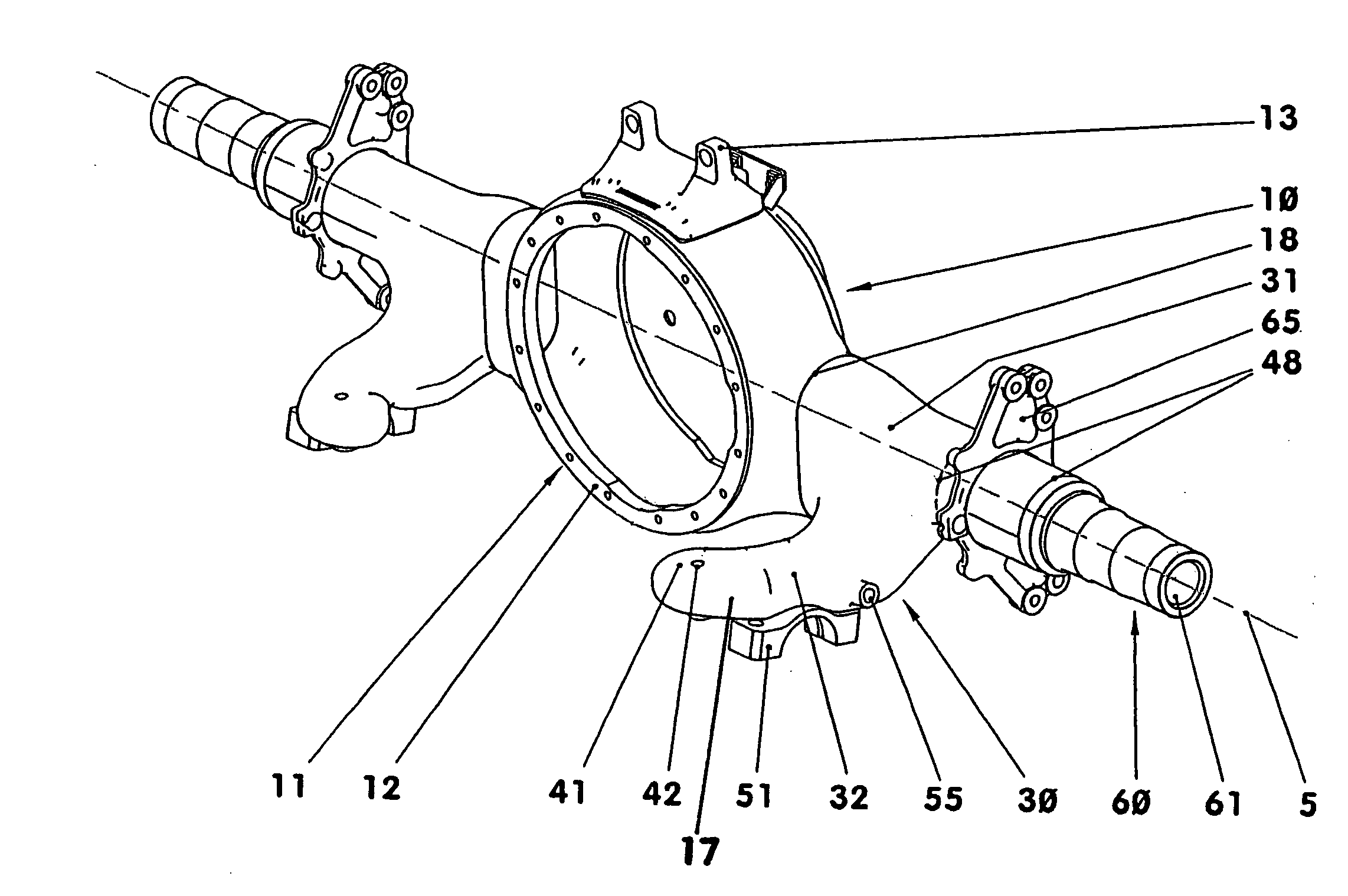
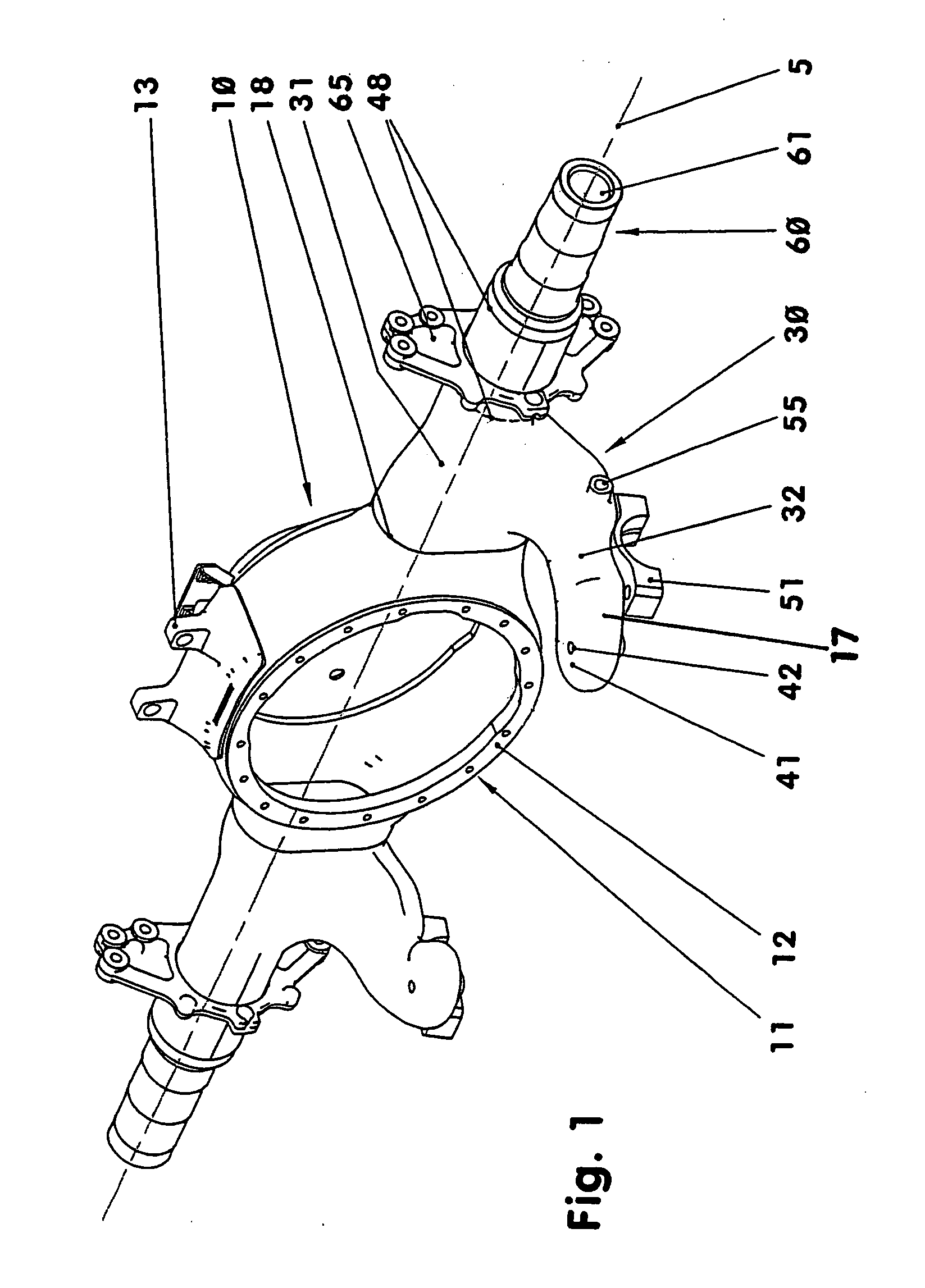
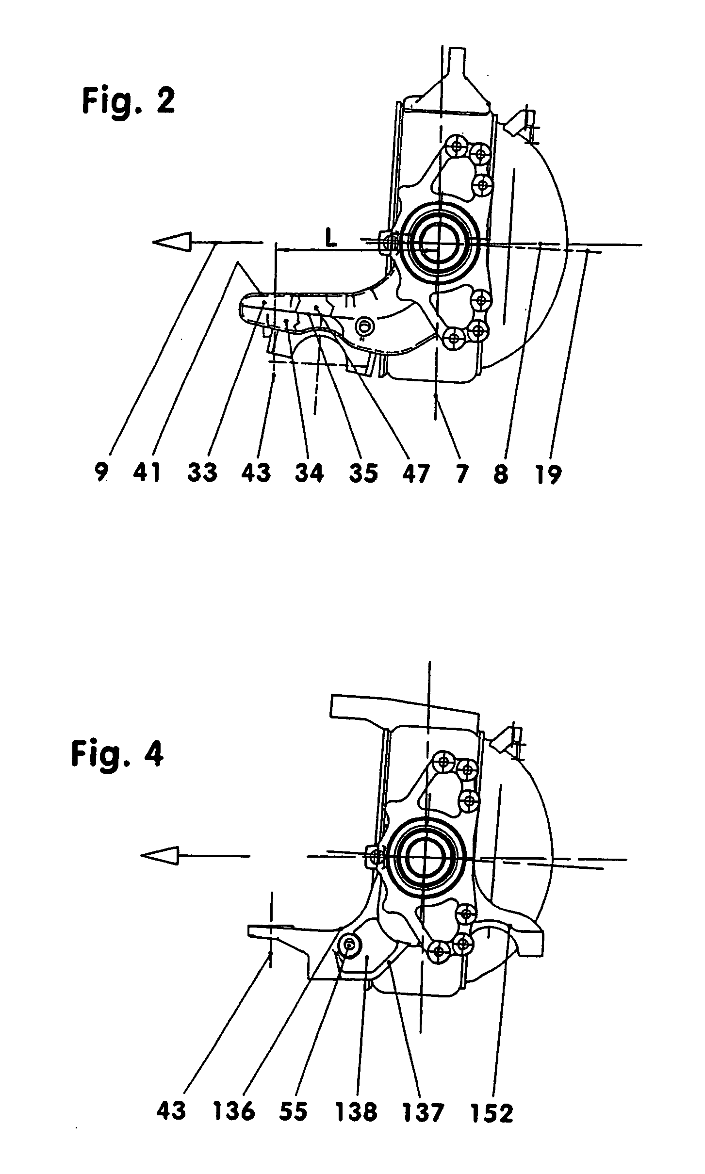
[0018] FIGS. 1 to 4 show examples of two different axle beams (10, 110), which may in each case be driven rigid axles of a commercial vehicle. Such an axle may also be a steered axle.

[0019] The axle beam (10) as shown in FIG. 1 comprises a center structure (12) including a differential housing (11), opposite axle tube sections 31 with spring brackets (30) and two axle journals (61) forming the outer axle beam end sections (60).

[0020] The differential housing (11), may be formed from sheet metal and form the center part of the axle beam (10). As shown in the figures it is provided with. A support bracket (13), which may be forged, for example. The axle beam (10) is supported via a wishbone (not shown) on the vehicle frame by way of this support bracket (13). At either side, the differential housing (10) has a large opening of rectangular cross section, for example. The corners of these cross sections are rounded. At least 60% of the vertical portion of these virtually oval cross se...


PUM


Abstract

In a rigid drive axle for a vehicle comprising an axle beam provided with a differential housing, at least two tubular axle sections extending in opposite directions from the differential housing and spring support brackets projecting laterally from the axle tube sections, the spring support brackets are integral parts of the axle tube sections facilitating adaptation to various automotive vehicles and forming a relatively low-weight structure which increases the ride comfort and driving safety and also provides for minimal tire wear.

Description

[0001] This is a CIP application of pending international application PCT / EP2005 / 009078 filed Aug. 23, 2005 and claiming the priority of German patent application 10 2004 041 437.0 filed Aug. 27, 2004BACKGROUND OF THE INVENTION [0002] The invention relates to a driven rigid axle for a vehicle, comprising an axle beam provided with a differential housing, at least two projecting spring brackets and outer axle end pieces in the form of axle journals. [0003] DE 296 16 257 U1 discloses a pneumatically sprung rigid axle for a vehicle, comprising a axle tube with trailing arms welded thereto. Trailing arms with corresponding socket holes are pushed onto both axle tubes from the two opposite ends, each of which forms an axle journal. The trailing arms are welded along the socket holes to the axle tubes and extend rearwardly beyond the axle tube. The free ends serve as seats for air springs. As a result, however, the trailing arm is subjected to bending stresses. In order to avoid weakening...

Claims


Application Information

Patent Timeline
IPC IPC(8): B60K17/16B60B37/00F16H57/02B60G9/00
CPCB60B35/006Y10T74/2188B60B2310/208B60B2310/302B60B2360/102B60B2360/141B60B2360/147B60B2900/116B60G9/00B60G11/27B60G11/28B60G2200/30B60G2202/152B60G2206/012B60G2206/31B60B35/16
Inventor HENZE, STEFFENSCHUTZ, KLAUSTOLLE, KAIWEBER, STEFFEN
Owner DAIMLER AG
Why Eureka
Try Eureka