Bulk cheese shredding system

Inactive Publication Date: 2007-08-30
JOHNSON CHARLES H
View PDF4 Cites 4 Cited by
  • Summary
  • Abstract
  • Description
  • Claims
  • Application Information

AI Technical Summary

Benefits of technology

[0027]It is thus another object of at least one embodiment of the invention to provide for a controlled passage of the grated cheese collecting in the drum, out of the drum after shredding.
[0028]The cheese shredder may include a feeder having an exit opening positioned within the drum for feeding an anti-caking material onto the shredded cheese within the drum.

Problems solved by technology

The cubes of cheese may tumble in contact with the disk exposing irregular surfaces to the rotating knives and resulting in undesirable variations in the shred length and the production of “fines” which collect unattractively at the bottom of the package.
Preparing the cubes o

Method used


Image

  • Bulk cheese shredding system
  • Bulk cheese shredding system
  • Bulk cheese shredding system

Examples


Embodiment Construction

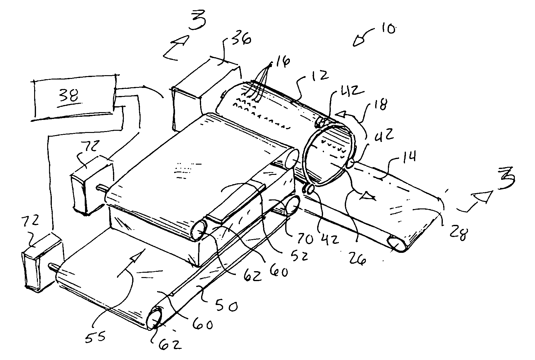
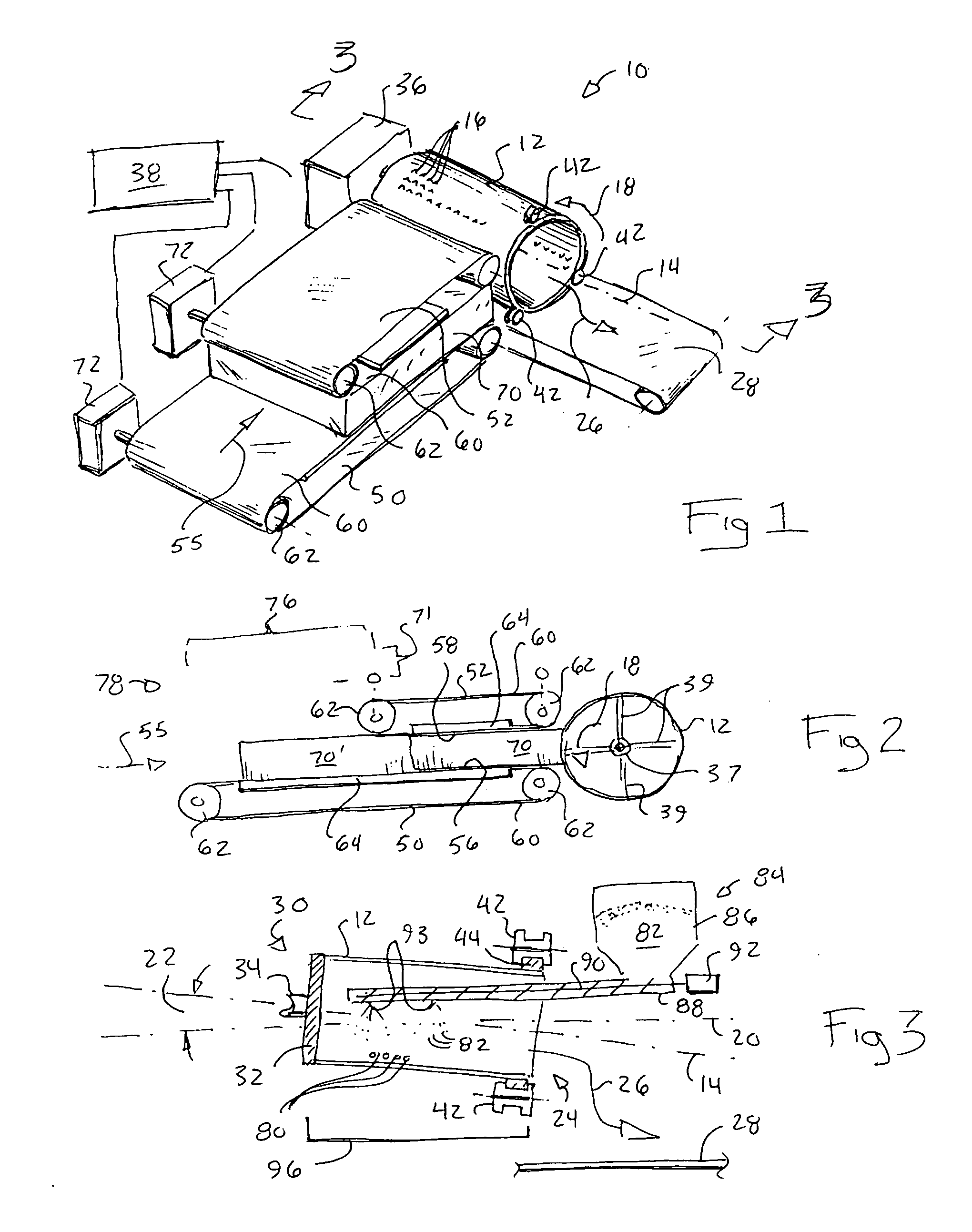
[0054]Referring now to FIG. 1, a cheese shredder 10 of the present invention employs a shredder drum 12 having a cylindrical shredding surface disposed along a drum axis 14. The drum 12 may, for example, be a stainless steel tube with the knife embossments 16 formed therein. The drum 12 will typically have a length along axis 14 of more than 20 inches and will have knife embossments 16 extending no less than this length so that a slab cut from a standard 640 pound block of cheese may be shredded in one pass when pressed against the side of the drum 12.

[0055]Each knife embossment 16 may be formed from a hole cut through the surface of the drum 12. A trailing edge of each hole is pressed outward and sharpened so that with forward rotation 18 of the drum 12, the edge will cut into cheese pressed against the drum 12 to cut shreds from the cheese. Knife embossments 16 of this type are well known in the art.

[0056]Referring now also to FIG. 3, the drum axis 14 may be tipped slightly with r...


PUM


Abstract

Conveyors to clamp the upper and lower surface of bulk slabs of cheese allowing precise control of feed rates against a drum shredder to promote uniform shred length without the need for cubing of the cheese prior to the shredding process. An anti-caking material may be placed in the drum to treat cheese shreds prior to their discharge.

Description

CROSS-REFERENCE TO RELATED APPLICATIONS[0001]- - -STATEMENT REGARDING FEDERALLY SPONSORED RESEARCH OR DEVELOPMENT[0002]- - -BRIEF SUMMARY OF THE INVENTION[0003]The present invention relates to food processing equipment and in particular to an industrial cheese shredding apparatus.[0004]Many consumers prefer the convenience of purchasing cheese in a shredded form. Such “pre-shredded” cheese is easier to serve and to distribute in cooking and eliminates the effort and hazard of shredding cheese at home.[0005]Currently, the bulk shredding of cheese for retail sales may use a commercial disk-type shredding machine. The rotating disk has a surface studded with embossed edges and is used to grate small blocks of cheese (typically two inch cubes) placed in contact with the disk.[0006]The cubes of cheese may tumble in contact with the disk exposing irregular surfaces to the rotating knives and resulting in undesirable variations in the shred length and the production of “fines” which collec...

Claims


Application Information

Patent Timeline
IPC IPC(8): A47J43/25
CPCA47J43/255
Inventor JOHNSON, CHARLES H.
Owner JOHNSON CHARLES H
Why Eureka
Try Eureka