Touch panel

a touch panel and touch technology, applied in the field of touch panels, can solve the problems of unstable operation and the above mentioned problems of conventional touch panels, and achieve the effects of avoiding loose fitness, convenient operation, and secure electrical connection

Inactive Publication Date: 2007-08-30
PANASONIC CORP
View PDF3 Cites 6 Cited by
  • Summary
  • Abstract
  • Description
  • Claims
  • Application Information

AI Technical Summary

Benefits of technology

[0016]With the touch panel of the invention, a polarizing plate is adhered to an upper surface of an upper substrate but within an outer periphery of a frame-like spacer. Because the polarizing plate is placed inside the outer periphery of the spacer, the substrate bends little even when the panel is exposed to a high temperature and high humidity environment, preventing the substrate from being peeled off from the spacer and avoiding a loose fitness between the substrate and wiring substrate 6, providing a touch panel of easy operation and secure electrical connection.

Problems solved by technology

Because of the structure, when the panel is exposed to a high temperature and high humidity environment, upper substrate 1 bends with contracted polarizing plate 7, peeling off an outer periphery of the substrate from spacer 5, and causing an operation unstable.
The conventional touch panel contains above mentioned problems.

Method used


Image

  • Touch panel
  • Touch panel
  • Touch panel

Examples


Embodiment Construction

[0021]The invention solves the conventional problems and provides a touch panel with stable operational performance and electrical connection even when it is exposed to a high temperature and high humidity environment.

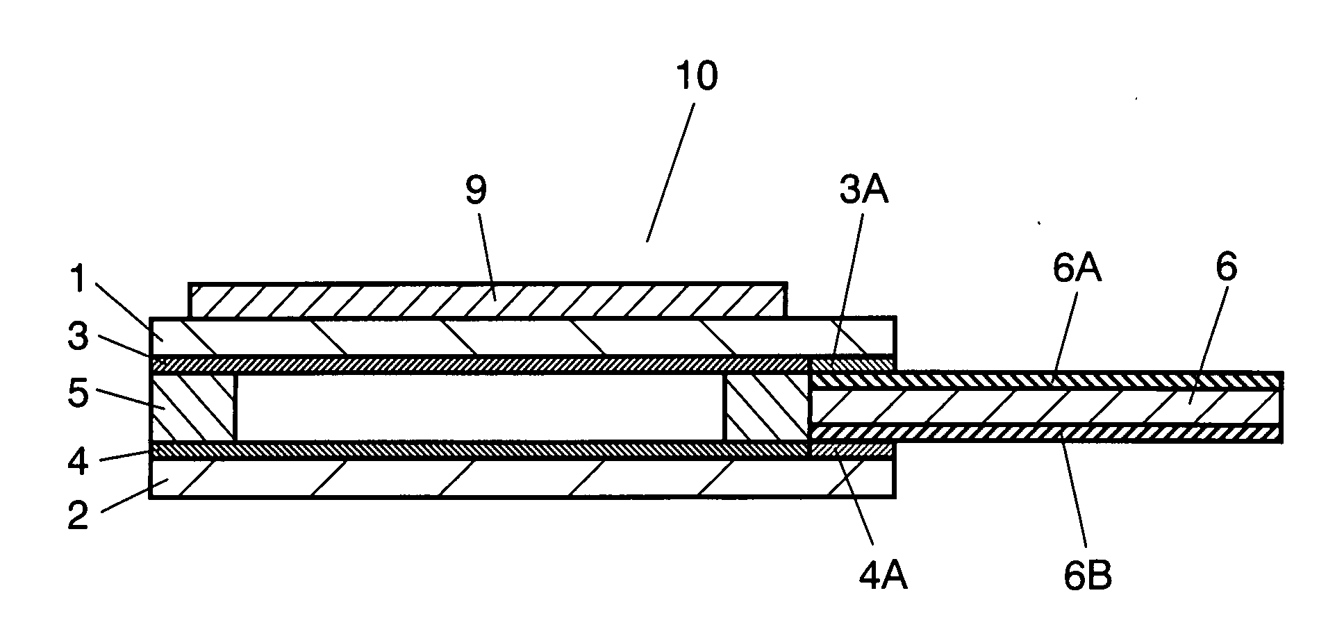
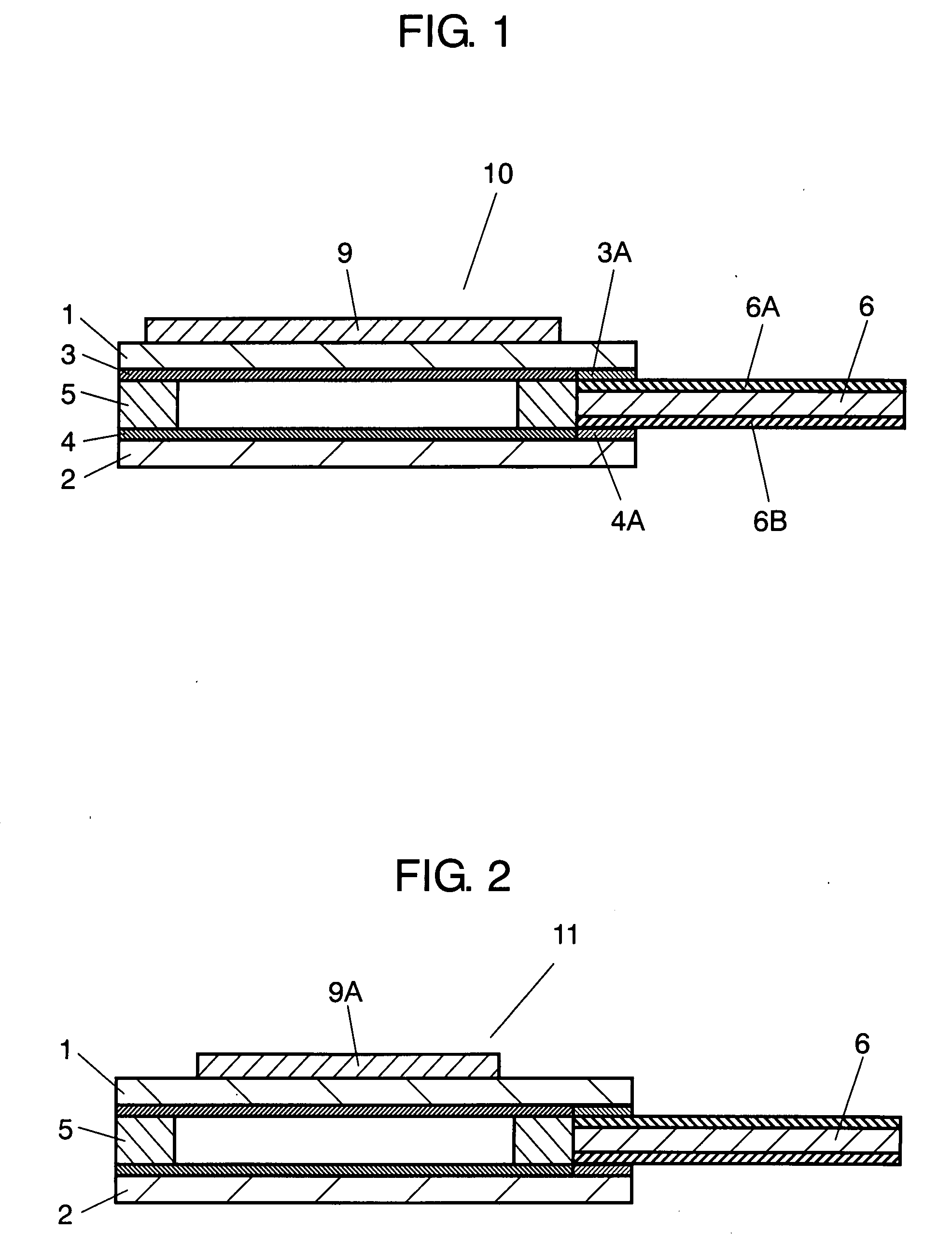
[0022]Following, an exemplary embodiment is explained with reference to FIGS. 1 and 2. Thickness is illustrated enlarged in the drawings for easy understanding of constitution.

[0023]For the part already explained in the background art, the same numerical reference is provided.

Exemplary Embodiment

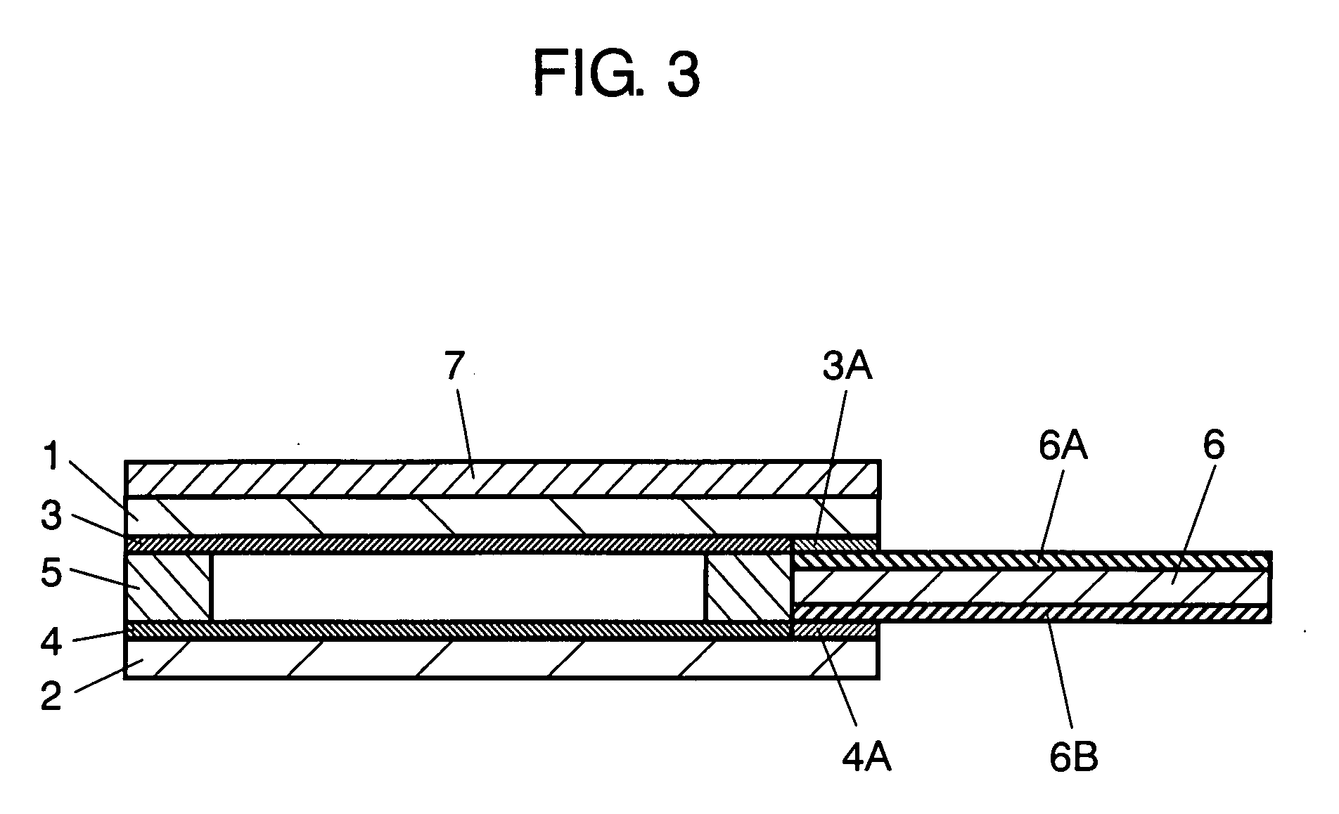
[0024]FIG. 1 is a cross sectional view of a touch panel according to an exemplary embodiment of the invention. In FIG. 1, upper substrate 1 is an optically isotropic and transparent substrate, a film made of plyestersulfone, polycycloolefin or the like. Lower substrate 2 is an optically isotropic and transparent substrate made of glass, polycarbonate, polyestersulfone or the like. Optically transparent upper conductive layer 3, made of indiumtin oxide, indium oxide or the like,...


PUM


Abstract

The touch panel of the invention includes an optically transparent upper substrate having an upper conductive layer formed on an undersurface thereof, an optically transparent lower substrate having a lower conductive layer formed on an upper surface thereof and facing the upper conductive layer with a predetermined space, a spacer in a frame shape disposed between the upper substrate and the lower substrate, and a polarizing plate adhered to an upper surface of the upper substrate, in which the polarizing plate is adhered to the upper surface of the upper substrate within the outer periphery of the spacer. Because the polarizing plate is attached to the upper surface of the upper substrate but within an outer periphery of the spacer, even when the panel is exposed to a high temperature and high humidity environment, the substrate is prevented from being peeled off the spacer and a loose fitness of wiring substrate is avoided, thus a touch panel of an easy operation and a secure electrical connection is obtained.

Description

FIELD OF THE INVENTION[0001]This invention relates to a touch panel which is used mainly for operating various electronic devices.BACKGROUND OF THE INVENTION[0002]In recent years, an electronic device including a portable phone and a car navigator tends to require much higher and a variety of functions. With this trend, a device having an optically transparent touch panel installed on a front panel of a display element such as a liquid crystal is increasing in number, in which the variety of functions is switched with the touch panel pressed by a finger or a pen, meanwhile a display of a display element can be recognized in a rear side of the panel.[0003]Following, such a conventional touch panel is explained with reference to FIG. 3. For easy understanding of its constitution, thickness of the panel is illustrated enlarged in the drawing.[0004]FIG. 3 is a cross sectional view of a conventional touch panel. In FIG. 3, upper substrate 1 and lower substrate 2 are a transparent substra...

Claims


Application Information

Patent Timeline
Patent Type & Authority Applications(United States)
IPC IPC(8): H01L23/544
CPCG06F3/045G02F1/13338
Inventor NAKANISHI, AKIRAMURAKAMI, TETSUOMATSUMOTO, KENICHIFUJII, SHOJI
Owner PANASONIC CORP
Why Eureka
Try Eureka