Eddy current type sensor for detecting conductor

a technology of eddy current type and conductor, which is applied in the direction of instruments, magnetic properties, hysteresis curve measurements, etc., can solve the problems of coil impedance, ambient temperature may exceed the maximum operating temperature of the pressure sensor, and the accuracy of the eddy current type sensor may decrease under such a high temperature environment, so as to accurately detect the conductor.

Active Publication Date: 2007-08-30
DENSO CORP +1
View PDF5 Cites 28 Cited by
  • Summary
  • Abstract
  • Description
  • Claims
  • Application Information

AI Technical Summary

Benefits of technology

[0010] The signal voltage has a first voltage value when the detection coil is separated from the conductor by a first distance and has a second voltage value when the detection coil is separated from the conductor by a second distance less than the first distance. A voltage difference between the first and second voltage values has a first difference value at a first temperature and has a second difference value at a second temperature less than the first temperature. The first and second difference values become equal to each other at a first frequency and a second frequency less than the first frequency. The oscillation frequency of the oscillator is set close to the first frequency or the second frequency. In such an approach, change in the voltage difference due to a change in temperature (at least between the first and second temperatures) can be reduced so that the sensor can accurately detect the conductor regardless of the temperature change.

Problems solved by technology

Further, although the ambient temperature of the centrifugal compressor is relatively low, the ambient temperature may exceed maximum operating temperature of the pressure sensor.
However, since the coil impedance changes with the temperature change, accuracy of the eddy current type sensor may decrease under such a high temperature environment.
Further, since the coil impedance slightly changes with the change in the eddy current, the change in the coil impedance due to the temperature change greatly affects the accuracy of the eddy current type sensor.

Method used


Image

  • Eddy current type sensor for detecting conductor
  • Eddy current type sensor for detecting conductor
  • Eddy current type sensor for detecting conductor

Examples


first embodiment

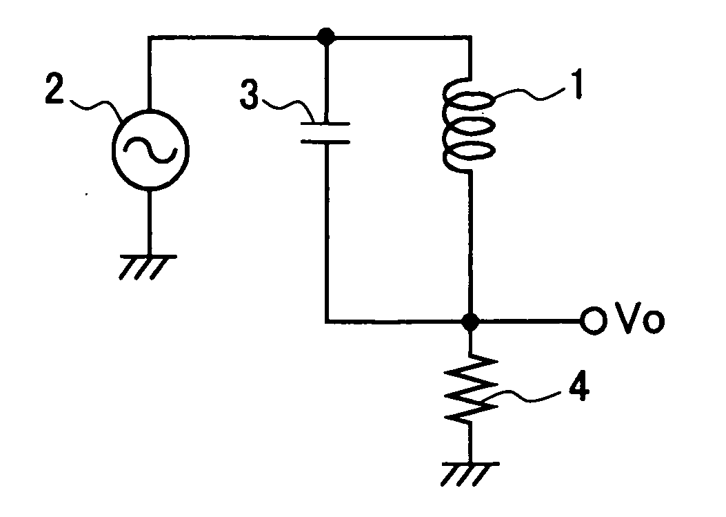
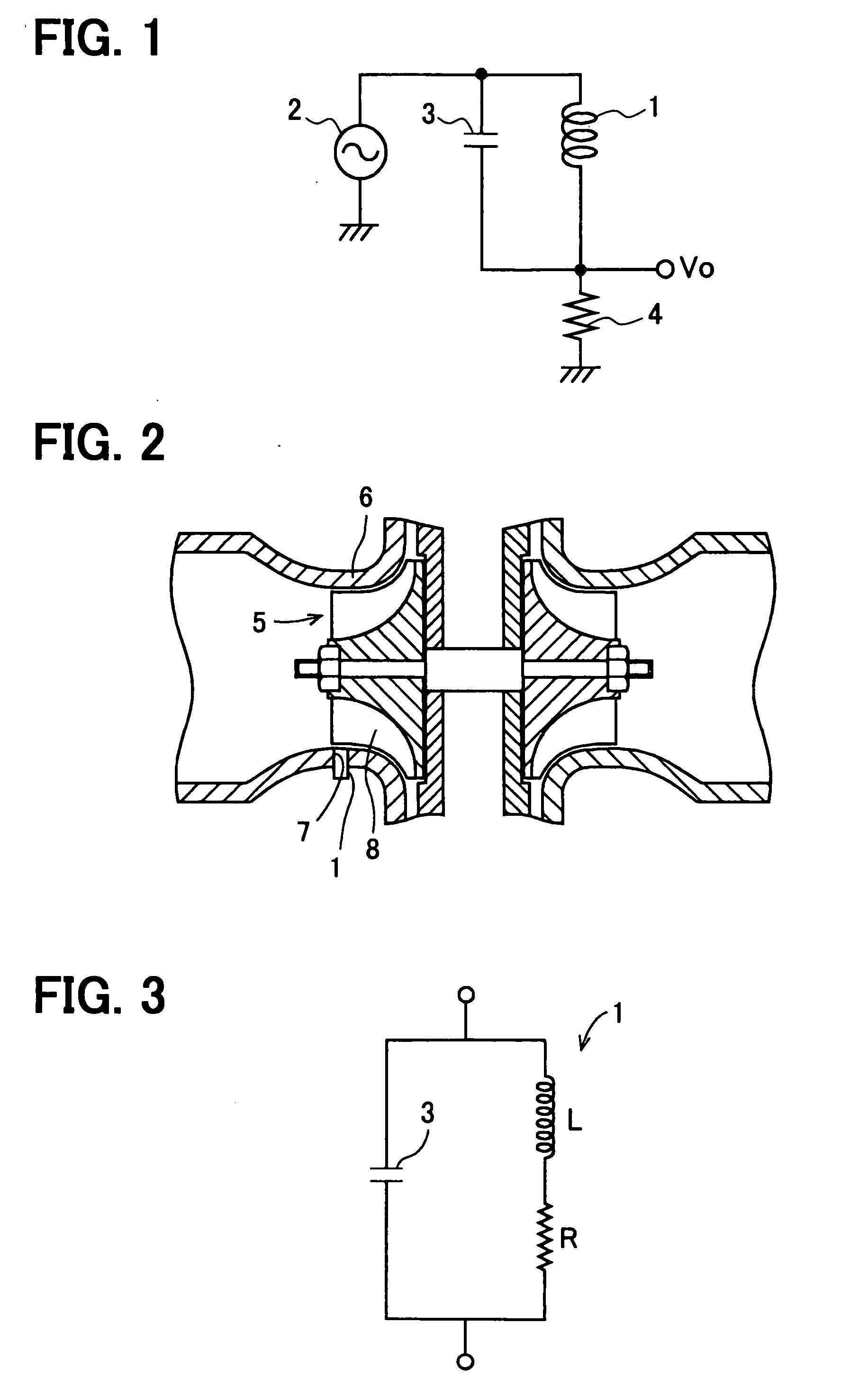
[0023] A main circuit of a turbocharger speed sensor according to a first embodiment of the present invention is shown in FIG. 1. The turbocharger speed sensor detects a rotational speed of a turbocharger by detecting a rotational speed of a centrifugal compressor 5 shown in FIG. 2. As shown in FIG. 1, the main circuit includes a detection coil 1, an oscillator 2, a capacitor 3, and a resistor 4. The detection coil 1 and the capacitor 3 are connected in parallel to form a parallel LC circuit having a resonant frequency fr. The oscillator 2 oscillates at an oscillation frequency f0. The resistor 4 is used to detect a signal voltage. The oscillation frequency f0 is set close to the resonant frequency fr.

[0024] The compressor 5 is housed in a casing 6 and has a blade 8 made of nonmagnetic aluminum alloy. A coil holder 7 is provided on an inner surface of the casing 6 and arranged outside the blade 8 in the radial direction. The detection coil 1 is received in the coil holder 7.

[0025]...

second embodiment

[0066] A pedestrian detection system according to a second embodiment of the present invention is shown in FIG. 11. The pedestrian detection system includes an eddy current proximity sensor 10, a collision sensor 20, a controller 40 having a microcomputer (not shown) and an A / D converter (not shown), a wheel speed sensor 50, and a pedestrian protection device 80 such as an airbag or a seat belt pretensioner. The eddy current proximity sensor 10 includes the main circuit shown in FIG. 1. When the detection coil 1 is placed in proximity to a conductor such as a metal pole, an eddy current is induced in the conductor. The inductance L of the detection coil 1 decreases due to the effect of the eddy current. As a result, the combined impedance Z of the LC circuit decreases. In contrast, when the detection coil 1 is placed in proximity to human body or an insulator, the combined impedance Z of the LC circuit decreases very little. Thus, the eddy current proximity sensor 10 can distinguish...


PUM


Abstract

An eddy current type sensor for detecting a conductor includes a LC circuit and an oscillator. The LC circuit has a coil and a capacitor connected in parallel with the coil. The oscillator supplies an alternating current of a predetermined oscillation frequency to the LC circuit. A signal voltage outputted from the LC circuit has a first voltage when the distance between the coil and the conductor is minimum and a second voltage when the distance between the coil and the conductor is maximum. A voltage difference between the first and second voltages has a first difference at a first temperature and has a second difference at a second temperature. The first and second differences become equal to each other at a first frequency and a second frequency. The oscillation frequency is set close to the first frequency or the second frequency.

Description

CROSS REFERENCE TO RELATED APPLICATION [0001] This application is based on and incorporates herein by reference Japanese Patent Application No. 2006-52437 filed on Feb. 28, 2006. FIELD OF THE INVENTION [0002] The present invention relates to an eddy current type sensor for detecting a conductor. BACKGROUND OF THE INVENTION [0003] A conventional turbocharger speed sensor detects a rotational speed of a turbocharger by detecting a rotational speed of a centrifugal compressor in the turbocharger, because the ambient temperature of the centrifugal compressor is relatively low. [0004] A turbocharger speed sensor disclosed in JP-2003-240788 includes a pressure sensor. The pressure sensor detects a periodic change in pressure caused by passage of an aluminum blade of the centrifugal compressor. The turbocharger speed sensor detects the rotational speed of the compressor based on the periodic pressure change. [0005] Another known turbocharger speed sensor detects the rotational speed of the...

Claims


Application Information

Patent Timeline
Patent Type & Authority Applications(United States)
IPC IPC(8): G01R33/14
CPCG01V3/102
Inventor SHIMOMURA, OSAMUNAKAMURA, TSUTOMUTAKEDA, KENJIMIZUTANI, AKITOSHIBAN, TAKAO
Owner DENSO CORP
Why Eureka
Try Eureka