
Liquid crystal display device

Inactive Publication Date: 2007-08-30
TOSHIBA MATSUSHITA DISPLAY TECH
View PDF17 Cites 34 Cited by
  • Summary
  • Abstract
  • Description
  • Claims
  • Application Information

AI Technical Summary

Benefits of technology

[0009]An object of the present invention is, in a MVA mode liquid crystal display, to suppress noise in display caused by variations of inclination directions of liquid crystal molecules, and to improve quality of display such as transmittivity and contrast.
[0011]In the present invention, the first structure is provided to the first electrode in a shape including a discontinuous portion therein, and the second structure is provided to the second electrode so as to face the discontinuous portion of the first structure. In a case where a voltage is applied to the first and second electrodes to generate an electric field in the liquid crystal layer, the first structure controls the inclination directions of the liquid crystal molecules, and the second structure controls the inclination directions of the liquid crystal molecules present in the discontinuous portion of the first structure. Furthermore, in a region where the first structure is divided, an amount of light passing through the liquid crystal layer increases, and the liquid crystal molecules are aligned more vertically so that light leakage is reduced.

Problems solved by technology

However, in the conventional liquid crystal display devices, there is a case where projections on a substrate affect the quality of display.
As a result, there is a problem that noise is caused in a display.
In addition, there is a problem that deterioration in verticalness of liquid crystal molecules causes contrast deterioration and light leakage.

Method used


Image

  • Liquid crystal display device
  • Liquid crystal display device
  • Liquid crystal display device

Examples


first embodiment

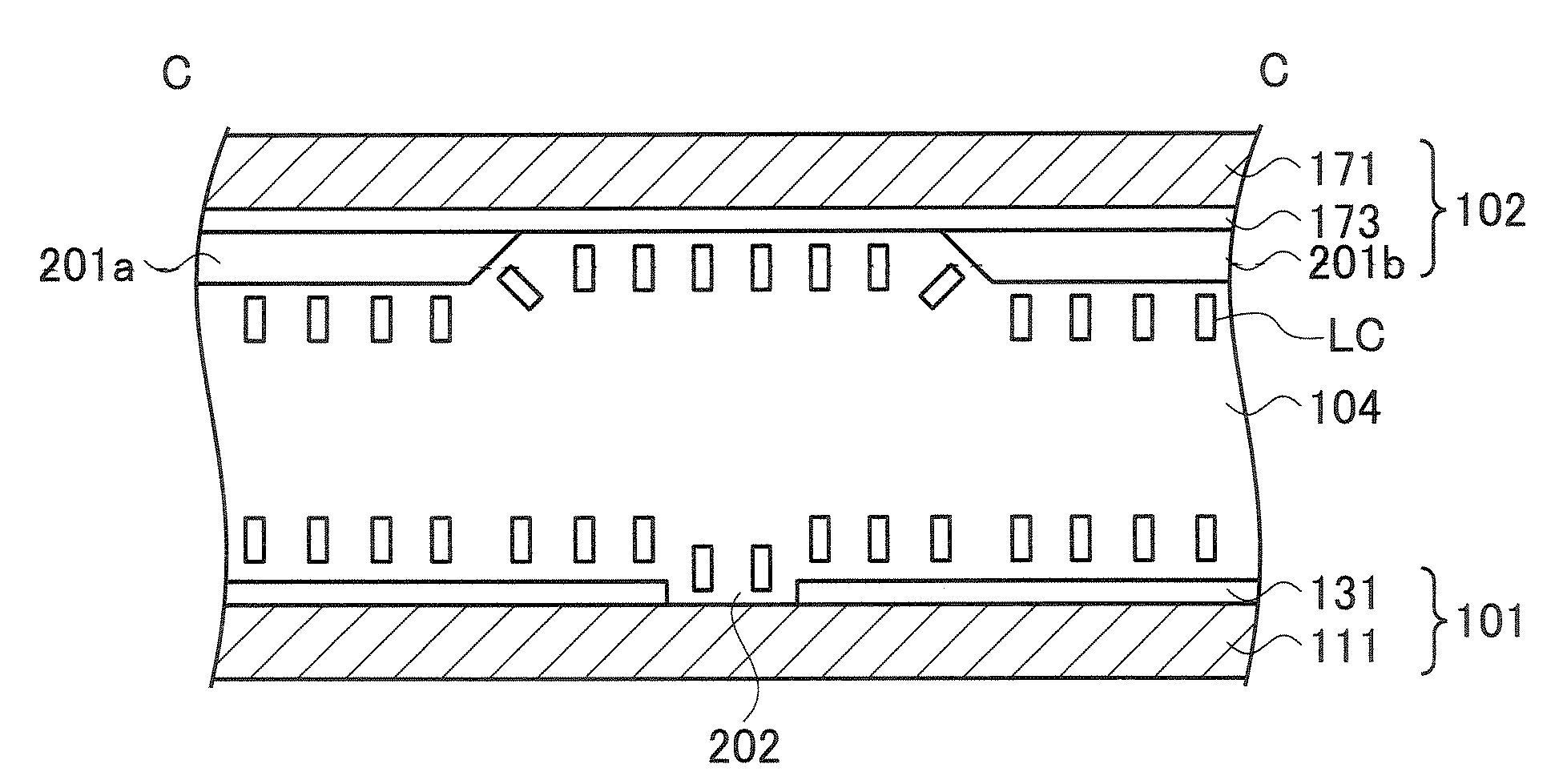
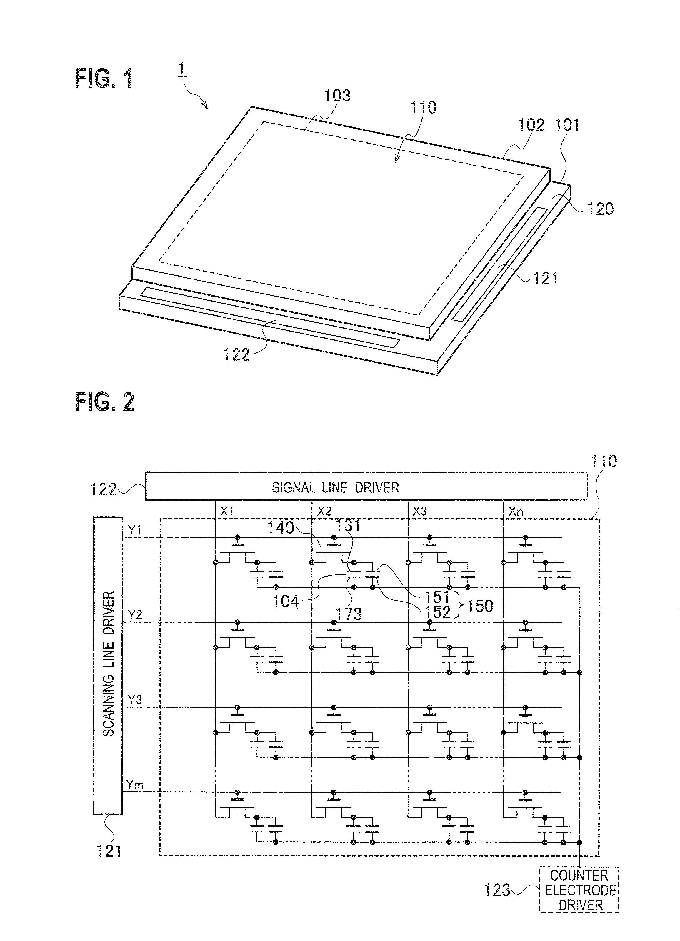
[0051]As shown in a perspective view of FIG. 1, a liquid crystal display device 1 of the present embodiment is provided with an array substrate 101 as a second substrate, an opposite substrate 102 as a first substrate disposed as facing the array substrate 101, and a liquid crystal layer 104 held in a gap between the substrates. The liquid crystal layer 104 is formed of liquid crystal molecules having a negative dielectric anisotropy. The liquid crystal molecules are aligned vertically to the two substrates. The array substrate 101 and the opposite substrate 102 are bonded together by a sealing member 103. A display region 110 is provided to a region defined by the sealing member 103. Furthermore, a circumferential region 120 is provided along an outer circumference of the display region 110. The liquid crystal display device 1 is a transmissive liquid crystal display device, and displays images by using light of an unillustrated backlight disposed in the back side of the array subs...

second embodiment

[0079]A basic configuration of a liquid crystal display device of a second embodiment is similar to that described in the first embodiment. Descriptions will be subsequently provided below for points different from the first embodiment.

[0080]As shown in a plan view of FIG. 13, the second embodiment is different from the first embodiment in the following points. Specifically, a first structure is slits 203a and 203b which is formed by partially removing the opposite electrode 173 in a shape including a discontinuous portion therein, instead of being projections 201a and 201b provided to an opposite electrode 173. A second structure is a slit 202 which faces a discontinuous portion of the slits 203a and 203b, and from which a pixel electrode 131 is partially removed.

[0081]All the portions of the slits 203a and 203b on the opposite electrode 173 extend in one direction. Here, the slits 203a and 203b extend in a direction parallel to a signal line X. The slits 203a and 203b are provided...

third embodiment

[0093]A basic configuration of a liquid crystal display device of a third embodiment is similar to that described in the first embodiment. Descriptions will be subsequently provided below mainly for points different from those of the first embodiment.

[0094]A liquid crystal display device of a third embodiment is a transflective liquid crystal display device having a multigap structure. As shown in a plan view of FIG. 21, this liquid crystal display device is provided to an opposite substrate as a first substrate and is further provided with a stepped portion 300 which adjusts a thickness of a liquid crystal layer. A pixel electrode as a second electrode is formed of a reflective electrode 2 and a transmissive electrode 131. The reflective electrode is disposed in a reflective region Ar where the stepped portion 300 makes the liquid crystal layer thinner than a second region. The transmissive electrode 131 is disposed in a transmissive region At where the liquid crystal layer is thic...


PUM


Abstract

In order to suppress noise in display, which would occur due to variations of inclination directions of liquid crystal molecules, and to improve display quality, a first structure in a shape having a discontinuous portion is provided to a first electrode, and a second structure is provided to a second electrode so as to face the discontinuous portion of the first structure. When a voltage is applied to the first and second electrodes to generate an electric field in a liquid crystal layer, the first structure controls the inclination directions of the liquid crystal molecules, and the second structure controls the inclination directions of the liquid crystal molecules existing in the discontinuous portion of the first structure. In the discontinuous portion of the first structure, the amount of light passing through the liquid crystal layer increases, and the liquid crystal molecules are aligned more vertically. Hence, light leakage is reduced.

Description

CROSS-REFERENCE TO RELATED APPLICATIONS[0001]This application is based upon and claims the benefit of priority from Japanese Patent Application No. 2006-48606 filed Feb. 24, 2006; the entire contents of which are incorporated herein by reference.BACKGROUND OF THE INVENTION[0002]1. Field of the Invention[0003]The present invention relates to a liquid crystal display device in which a liquid crystal having a negative dielectric anisotropy is used.[0004]2. Description of the Related Art[0005]In recent years, there has been proposed a Vertical Alignment mode liquid crystal display device in which a liquid crystal having a negative dielectric anisotropy is used. In this liquid crystal display device, liquid crystal molecules are aligned vertically to a substrate by using an alignment layer so that a birefringence of a liquid crystal layer is substantially zero. Thereby, sufficient black display can be achieved and high contrast can be concurrently obtained.[0006]Moreover, a liquid crysta...

Claims


Application Information

Patent Timeline
IPC IPC(8): G02F1/1337C09K19/02
CPCG02F1/133707G02F1/1393G02F1/1362G02F1/134309
Inventor HIROSAWA, JINYOSHIDA, NORIHIROTAKEDA, ARIHIROSUWA, REIKOKIMURA, HIROYUKITABATAKE, HIROSHIMORITA, YUUKI
Owner TOSHIBA MATSUSHITA DISPLAY TECH
Features
  • Generate Ideas
  • Intellectual Property
  • Life Sciences
  • Materials
  • Tech Scout
  • Unparalleled Data Quality
  • Higher Quality Content
  • 60% Fewer Hallucinations
Learn More