
Structure of interfolding machine with adjustable cut-off

a technology of cutting-off and folding machine, which is applied in the direction of paper/cardboard containers, packaging, transportation and packaging, etc., can solve the problems that the roller type is not suitable for interfolding machines, and achieve the effect of diffecting production

Inactive Publication Date: 2007-08-30
MTC MACCINE TRASFORMAZIONE CARTA SRL
View PDF15 Cites 26 Cited by
  • Summary
  • Abstract
  • Description
  • Claims
  • Application Information

AI Technical Summary

Benefits of technology

The present invention provides an interfolding machine structure that allows for easy and flexible production of stacks of interfolded sheets with different lengths and types, even while maintaining a same pack width. The machine has a frame with a cutting section, a transfer roller, and an interfolding section with folding rollers. The cutting section has a modular structure that can be easily replaced with different cut-off versions. The machine also has means for overlapping sheets, a separating section, and a moving mechanism for conveying partially overlapped sheets. The interfolding machine is highly flexible and can change both the length of sheets and the pack width independently.

Problems solved by technology

Machines exist capable of adjusting the cut-off using cutting rollers with several retractable knives (see EP1514677), and that can selectively exit or withdraw thus changing the cutting length: this type of rollers, however, is not appropriate for interfolding machines of “multifold” type, which normally provide one stream of sheets of paper.
In fact, in these machines it is not enough to adjust the cut-off by changing only the number of knives, but it would be necessary to change other parts of the machine.

Method used


Image

  • Structure of interfolding machine with adjustable cut-off
  • Structure of interfolding machine with adjustable cut-off
  • Structure of interfolding machine with adjustable cut-off

Examples


Embodiment Construction

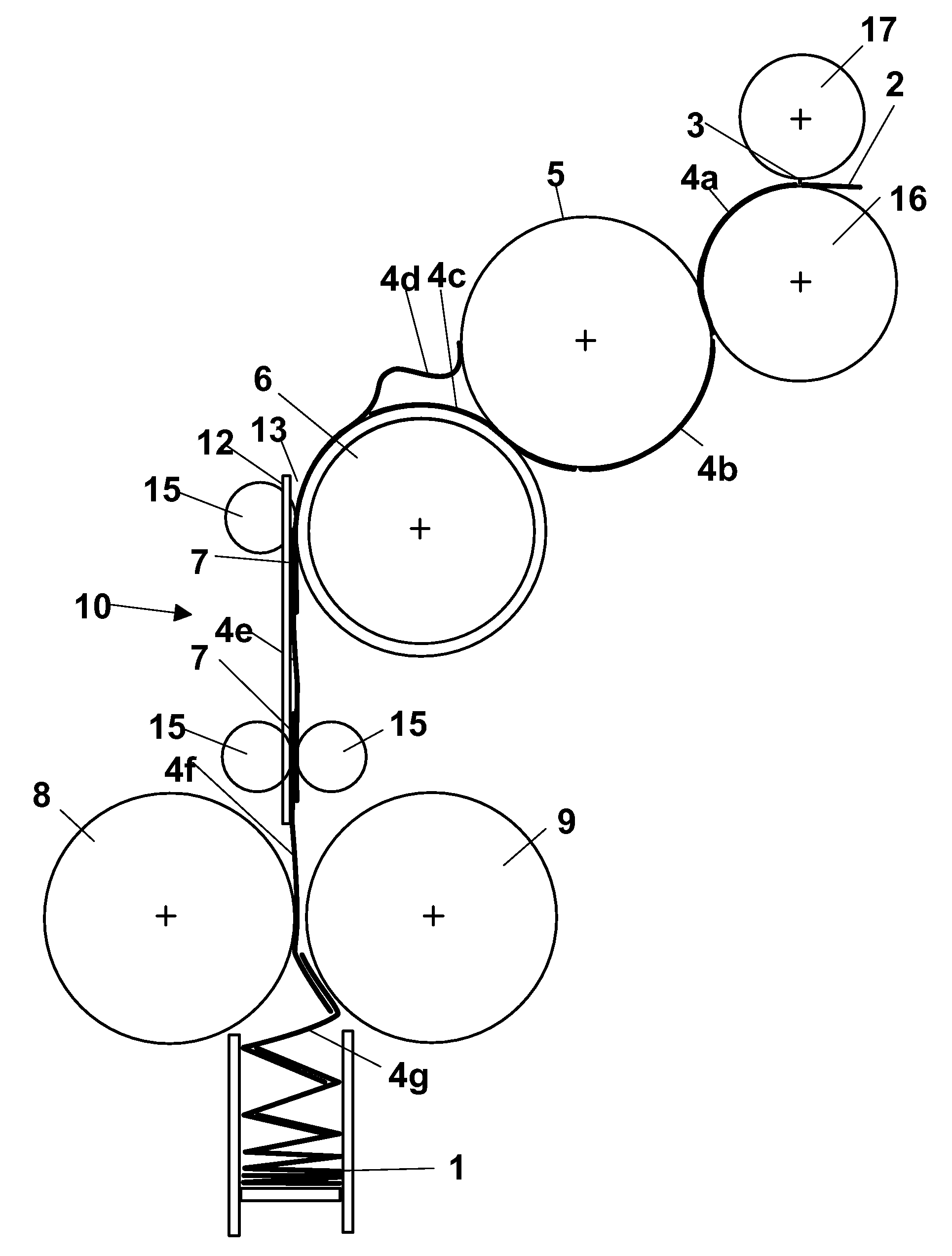
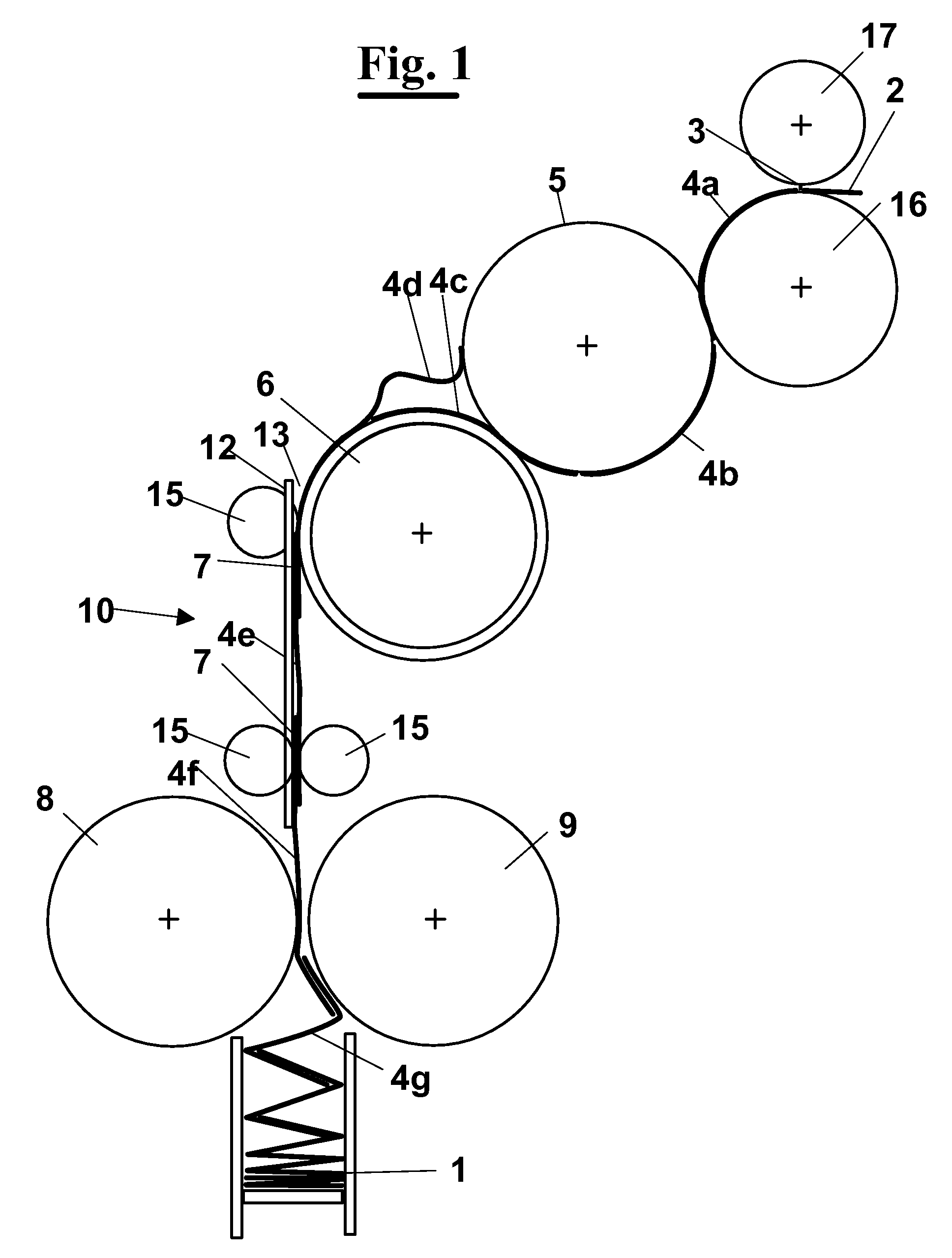
[0047]With reference to FIG. 1, an interfolding machine of sheet material for making a stack of interfolded sheets 1 uses at least one web 2 of material to interfold, for example paper, non woven fabric fed by means of feeding rollers 41-44. The web 2 is cut by a blade 3 of a cutting roller 17 into sheets of predetermined length. In particular, the blade 3 acts on a cutting roller 16. The cutter, in addition to a roller type, can be also formed without fixed blades and having alternated movement with respect to the cutting roller 16.

[0048]The cut sheets, all alike, which are carried along the machine are indicated as 4a, 4b, 4c, 4d, 4e, 4f, 4g, starting from the cutting point under the cutter 3 up to the point where they are interfolded.

[0049]As well known, at first, the cut sheets 4a, 4b proceed on a first roller 5 that rotates at a first speed. Then they pass on a second roller 6, called “overlap” roller, which rotates at a second speed less than the first. This way, owing to this...


PUM

PropertyMeasurementUnit
speedaaaaaaaaaa
lengthaaaaaaaaaa
areaaaaaaaaaaa

Abstract

An interfolding machine (100) having a modular structure and with variable cut-off, having a frame (21) comprising a first plate (21a) and a second plate (21b), parallel to each other, interconnected by means of beams (25). Between the plates (21a and 21b) folding rollers (8 and 9), means for moving (10) and an overlap roller (6), are arranged. Each plate (21a, or 21b), has a complementary shape to a respective upper plate (31a, or 31b). The higher plates (31a and 31b) are connected by means of beams (35) among one another. Between the plates (31a and 31b) instead the cutting roller (16), the transfer roller (5) and the cutter (17) with the blade (3) are arranged. This way, a modular portion (30) is formed removable independently from a main portion (20) of the frame. Alternatively, the removable portion (30) can comprise the only cutting roller (16) and the cutter (17) with the blade (3). Alternatively, the only transfer roller (5) may be provided. The advantage of the invention is that the removable portion brings with it gearings, bearings, supports, etc. of the substituted rollers, and it is exchanged with another equivalent but with different cut-off with a machine stop that is very short. The removable portion (30) can be slidingly mounted on longitudinal guides (36). This assists its removal from the working position, and provides a change with another removable portion (30) provided with rollers (16, 17 and 5) of diameter corresponding to the length of the interfolded sheets of the final stack.

Description

FIELD OF THE INVENTION[0001]The present invention relates to the production of paper material in stacks of interfolded sheets, and, in particular, it relates to a structure of interfolding machine adapted to process sheets of different length.BACKGROUND OF THE INVENTION[0002]As well known, in the paper converting industry a variety of types is used of machines and of processes for making paper tissues, paper towels and similar articles in stacks of a certain height of interfolded sheets.[0003]They are obtained stacking the sheets in an “interfolded” way, i.e. at each fold a wing of the previous sheet and a wing of a next stack sheet engage with each other. This way, when drawing a sheet from a package, at the moment of the use, also a wing of a next stack sheet is dragged up to protruding from the package, with subsequent practical employment for certain types of users. Among possible interfolding ways the L-type, with 2 folds (single fold), or the Z or W types, respectively with 3 ...

Claims


Application Information

Patent Timeline
Patent Type & Authority Applications(United States)
IPC IPC(8): B31B1/14
CPCB65H45/24B65H2601/324B65H2402/10B65H29/6618
Inventor DE MATTEIS, ALESSANDRO
Owner MTC MACCINE TRASFORMAZIONE CARTA SRL
Learn More