Blood pressure cuffs

a technology cuffs, which is applied in the field of blood pressure cuffs, can solve the problems of difficult to discern the exact timing and magnitude of the wave, cumbersome procedures, and often contained unwanted noise in signals, and achieves the effect of convenient manufacture, application and us

Inactive Publication Date: 2007-08-30
PULSECOR LTD
View PDF21 Cites 38 Cited by
  • Summary
  • Abstract
  • Description
  • Claims
  • Application Information

AI Technical Summary

Benefits of technology

[0014]It is therefore an object of the present invention to provide a blood pressure cuff, incorporating one or more low-frequency, wideband external pulse sensors, which is convenient to manufacture, apply and use in connection with a system and method for non-invasive cardiovascular assessment of a patient.
[0015]It is a further object of the present invention to provide a blood pressure cuff of the above-noted type, which is robust and produces clear, noise-free signals in a clinical environment.

Problems solved by technology

These reflection waves are identifiable in arterial pressure tracings, but the exact timing and magnitude of the waves are difficult to discern.
While this procedure yielded usable signals, the procedure was cumbersome in practice and the signals frequently contained unwanted noise due to artifacts and the like.
However, these sensors do not provide the low-frequency signals required for the cardiovascular assessment described above.

Method used


Image

  • Blood pressure cuffs
  • Blood pressure cuffs
  • Blood pressure cuffs

Examples


Embodiment Construction

[0039]The preferred embodiments of the present invention will now be described with reference to FIGS. 1-15 of the drawings. Identical elements in the various figures are designated with the same reference numerals.

General Principles:

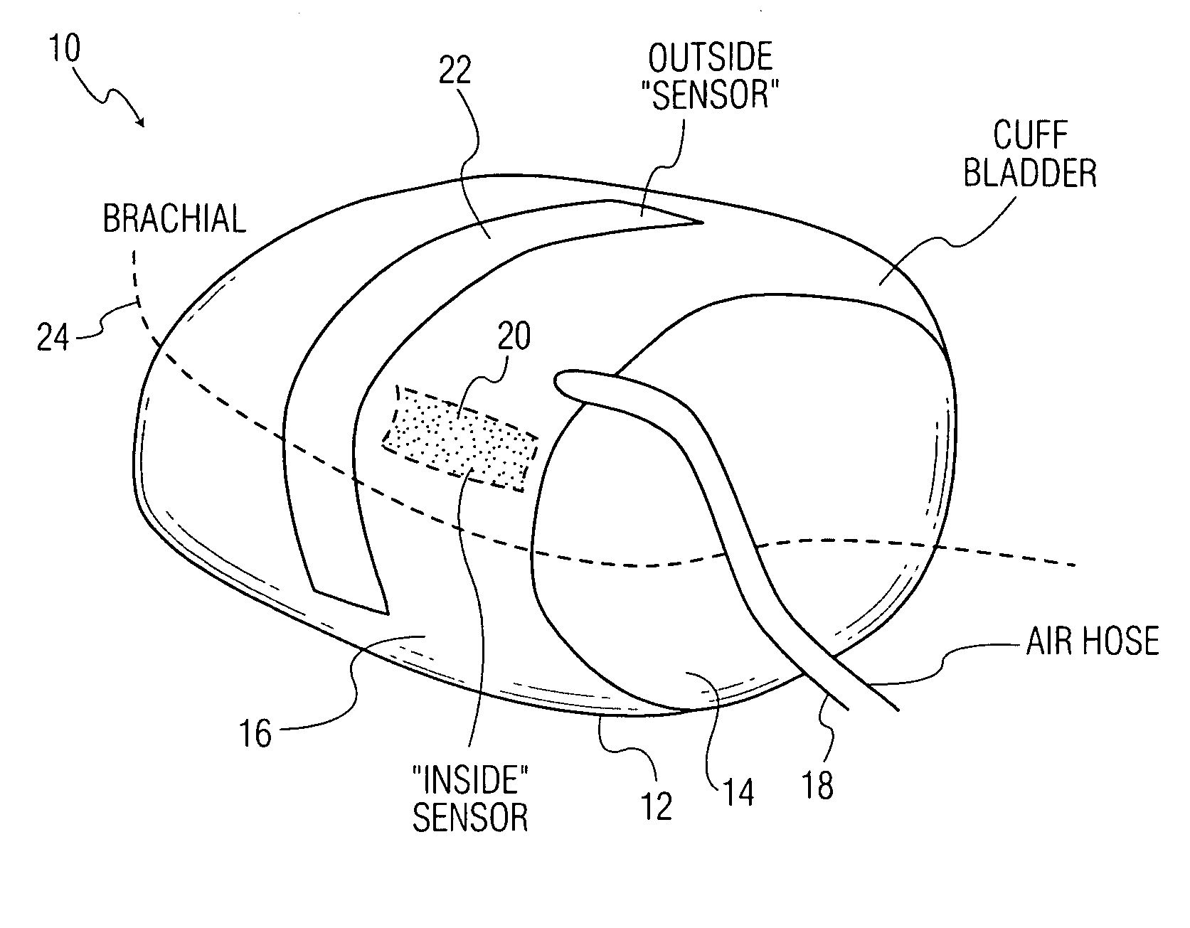
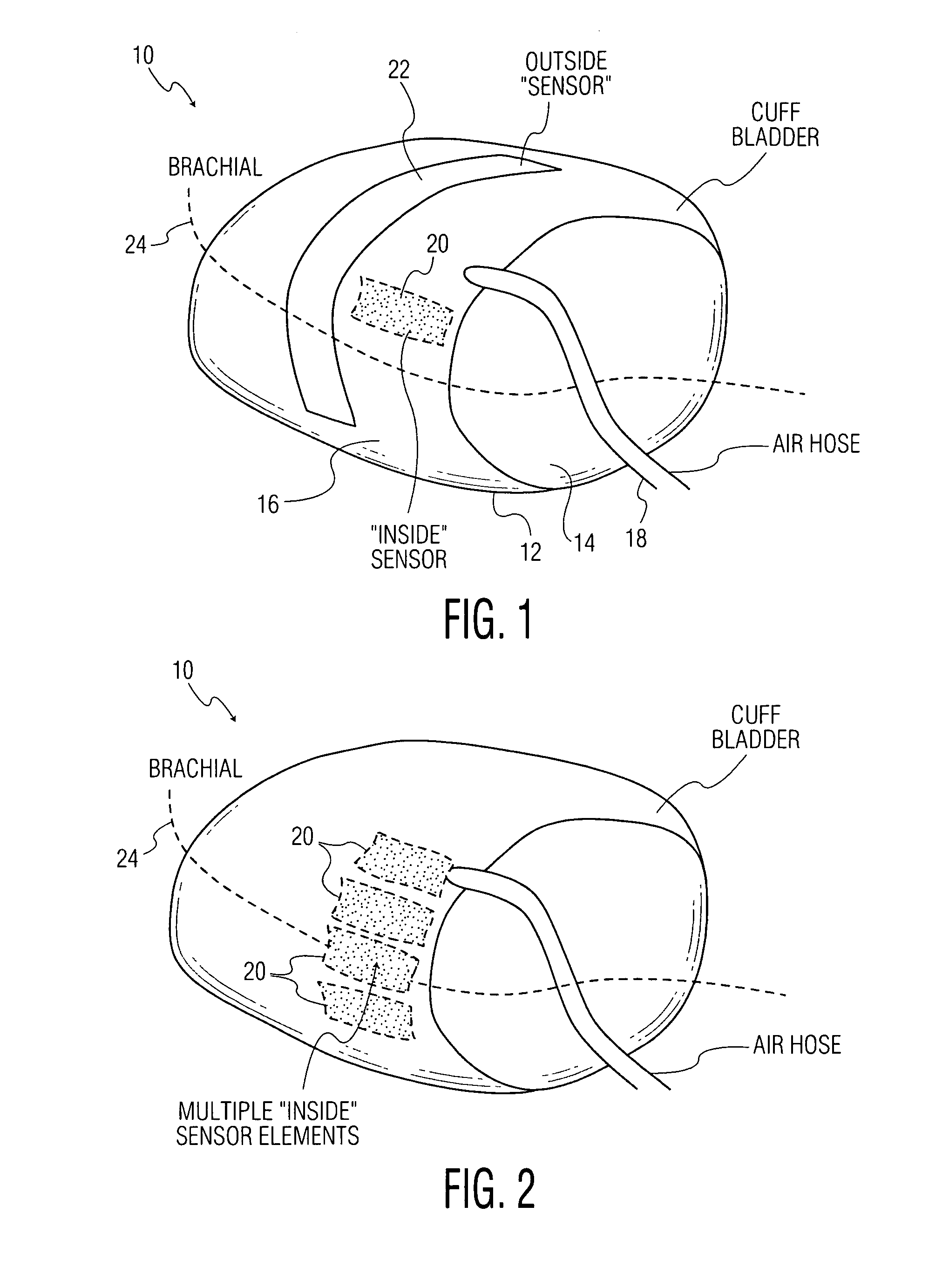
[0040]The general layout of the blood pressure cuff according to the present invention is illustrated in FIG. 1. The cuff 10 includes a flexible, hollow bladder 12 adapted to surround an arm of a patient, which has an inside external surface 14 adapted to apply pressure to the surface of the arm, an outside external surface 16 opposite the inside surface, and an inlet tube 18 for receiving a fluid to cause the bladder to expand.

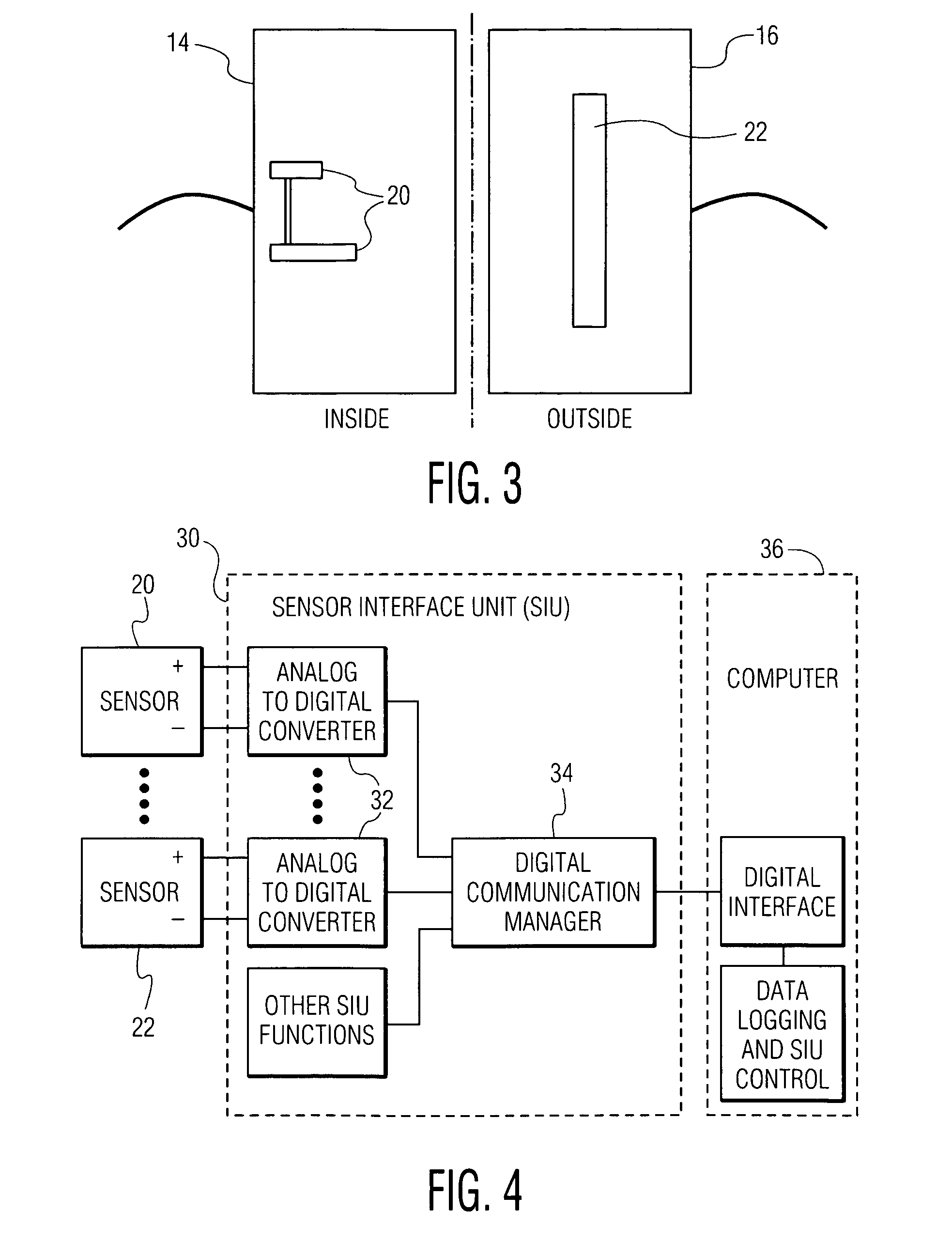
[0041]An “inside” sensor element 20 (shown in a dotted outline) is affixed, e.g., by a suitable adhesive or by welding, to the inside surface 14 of the cuff bladder that is pressed against the arm when the cuff is inflated. An “outside” sensor element 22 is affixed to the outside surface 16 of the cuff bladder; e.g., by an adhesi...


PUM


Abstract

A blood pressure cuff includes:(a) a flexible, hollow bladder adapted to surround the arm of the patient, which has an inside surface adapted to apply pressure to a surface of the arm above an artery, an outside surface opposite this inside surface, and an inlet line for receiving a fluid to cause the bladder to expand;(b) at least one first sensor element arranged on a inside and / or outside surface of the bladder in a location adjacent the artery when the bladder is in its operative position surrounding the patient's arm; and possibly also(c) at least one second sensor element arranged on a surface of the bladder that is opposite to the surface on which the first sensor element is disposed, and in a location adjacent the artery when the bladder is in its operative position surrounding the patient's arm. The sensor elements each comprise an elongate thin-film strip which transduces mechanical vibrations and produces an electrical signal representing these vibrations, normally in the range of 0 to 100 Hz.

Description

CROSS-REFERENCE TO RELATED APPLICATIONS[0001]The present application discloses subjected matter which is related to that disclosed in the prior U.S. patent application Ser. No. 11 / 358,283, filed Feb. 21, 2006, and entitled “SYSTEM AND METHOD FOR NON-INVASIVE CARDIOVASCULAR ASSESSMENT FROM SUPRA-SYSTOLIC SIGNALS OBTAINED WITH A WIDEBAND EXTERNAL PULSE TRANSDUCER IN A BLOOD PRESSURE CUFF” (which prior application is incorporated herein by reference). The present application also claims priority from the U.S. Provisional Patent Application Ser. No. 60 / 777,418 (Sharrock 207), filed Feb. 28, 2006, and entitled “IMPROVEMENTS IN BLOOD PRESSURE CUFF SENSORS”.BACKGROUND OF THE INVENTION[0002]The present invention relates to a blood pressure cuff of the type conventionally used in a sphygmomanometer to measure blood pressure according to the Korotkoff method. More specifically, the invention concerns blood pressure cuff that is specifically designed for non-invasive cardiovascular assessment ...

Claims


Application Information

Patent Timeline
Patent Type & Authority Applications(United States)
IPC IPC(8): A61B5/02
CPCA61B5/02208A61B5/02233A61B2562/227A61B2562/225A61B2562/0261
Inventor LOWE, ANDREW
Owner PULSECOR LTD
Why Eureka
Try Eureka