Hinged stator core

a stator core and twisted technology, applied in the direction of dynamo-electric machines, electrical equipment, magnetic circuit shapes/forms/construction, etc., can solve the problems of disengagement, difficult individual iron cores, and well connected ones, and achieve the effect of convenient wire winding, improved torsional strength, and compact wound wires

Active Publication Date: 2019-05-23
ZHEJIANG LINIX MOTOR
View PDF9 Cites 0 Cited by
  • Summary
  • Abstract
  • Description
  • Claims
  • Application Information

AI Technical Summary

Benefits of technology

[0010]Preferably, an inner rim of the internal yoke segment is arranged linearly and is in smooth connection to the teeth. That is, a surface where the individual iron core is fitted with a coil framework is flat. This can provide for a more appropriate winding layout in order to facilitate the wire winding, and also can make the wound wire more compact.
[0011]Preferably, the individual iron core has a plurality of through slots which axially runs through the individual iron core along the rotor shaft, and the through slots are elongated; and the individual iron core comprises a plurality of first slots and a plurality of second slots; there is an included angle between one of the first slots and one of the second slots; the first slots are arranged symmetrically about the second slots; and the first slots are located on the yoke. The arrangement of the first slots and the second slots can greatly improve the torsional strength and ensure the peeling strength of the whole core.
[0012]Preferably, there are two first slots and two second slots, the second slots are located on a symmetric line of the teeth, and the first slots and the second slots are vertical to each other. Such an arrangement maximizes the torsional strength and ensures the peeling strength of the whole core.
[0013]Preferably, an inner rim of the hinge of the individual iron core has a same shape as an outer rim of the internal yoke segment of an adjacent individual iron core and an inner rim of the hinge slot, the hinge is fitted with the hinge slot so that the inner edge of the hinge of one individual iron core is tightly and seamlessly connected to the outer edge of the internal yoke segment of an adjacent individual iron core. The tight and seamless connection of the inner edge of the hinge of one individual iron core to the outer edge of the internal yoke segment of an adjacent individual iron core ensures the integrity of the magnetic circuit of the motor.
[0014]Preferably, gaps are formed between the teeth of the individual iron cores of the stator core. Such an arrangement enhances the overload capacity with the same power while ensuring the cogging torque.
[0015]The present invention has the advantages of convenient manufacturing and processing, more convenient wire winding, and high integrity of the magnetic circuit.

Problems solved by technology

It is difficult for the individual iron cores, which are well connected, to disengage from each other along the rotation direction of the rotor shaft.

Method used


Image

  • Hinged stator core

Examples


Embodiment Construction

[0019]The present invention will be further described below by specific embodiments with reference to accompanying drawings.

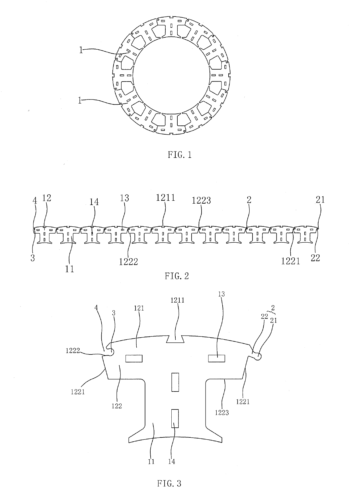
[0020]As shown in FIGS. 1, 2 and 3, a hinged stator core in the present invention consists of twelve individual iron cores 1 each comprising teeth 11 on an inner side and a yoke 12 on an outer side; two adjacent individual iron cores 1 are connected by a hinge structure comprising a hinge 2 and a hinge slot 3 fitted with the hinge, with both the hinge 2 and the hinge slot 3 being arranged on the yoke 12 of the individual iron core; each individual iron core 1 has one hinge 2 and one hinge slot 3; the hinge 2 is arranged on a side, which rotates about the rotor shaft clockwise, of the yoke 12 of the individual iron core, and the hinge slot 3 is arranged on a side, which rotates about the rotor shaft counterclockwise, of the yoke 12 of the individual iron core; and the individual iron cores 1 have a same structure, size and shape.

[0021]The hinge 2 consists of a f...


PUM


Abstract

The present invention discloses a hinged stator core. The hinged stator core consists of a plurality of individual iron cores each comprising teeth on an inner side and a yoke on an outer side; two adjacent individual iron cores are connected by a hinge structure comprising a hinge and a hinge slot fitted with the hinge, with both the hinge and the hinge slot being arranged on the yoke of the individual iron core; the hinge and the hinge slot are arranged on a side, which rotates about a rotor shaft clockwise and/or on a side, which rotates about a rotor shaft counterclockwise, of the yoke of the individual iron core; the hinge consists of a fitting segment fitted with the hinge slot and a connecting segment for connecting the fitting segment with the yoke; the fitting segment has a circular or segmental shape along a radial cross-section of the rotor shaft; the hinge slot has an arced shape along the radial cross-section of the rotor shaft; and both a center of a circle of the fitting segment of the hinge and a center of a circle of the hinge slot are in the circumference of a circle taking a center of the stator core as its center. The present invention has the advantages of convenient manufacturing and processing, more convenient wire winding, and high integrity of the magnetic circuit.

Description

TECHNICAL FIELD OF THE INVENTION[0001]The present invention relates to a stator core and in particular to a hinged stator core.BACKGROUND OF THE INVENTION[0002]As an important component of a motor, the motor stator comprises a stator core, a stator winding and a housing. A conventional stator core is structured in an entire circle and the entire circle cannot be separated. A desired number of slots are uniformly distributed on the entire circle. For such a conventional stator core, the stator core is obtained by directly stamping a plurality of silicon steel sheets by a stamping press. Although this method is fast and convenient for the production of the stator core, it is quite difficult to wind the wire onto the stator core structured in an entire circle. Material waste is caused, and the way of winding directly influences the working efficiency of the motor. Chinese Patent Application No. 201710109881.4 disclosed a stator core consisting of a plurality of individual iron cores. T...

Claims


Application Information

Patent Timeline
Patent Type & Authority Applications(United States)
IPC IPC(8): H02K1/14
CPCH02K1/148H02K1/16H02K1/165H02K2201/15
Inventor GE, JIANLIANGWANG, TINGJIANG, HAOJIEWANG, SHUAI
Owner ZHEJIANG LINIX MOTOR
Why Eureka
Try Eureka