
Apparatus and method of shaping an intervertebral space

Inactive Publication Date: 2007-08-30
VERMILLION TECH
View PDF9 Cites 27 Cited by
  • Summary
  • Abstract
  • Description
  • Claims
  • Application Information

AI Technical Summary

Benefits of technology

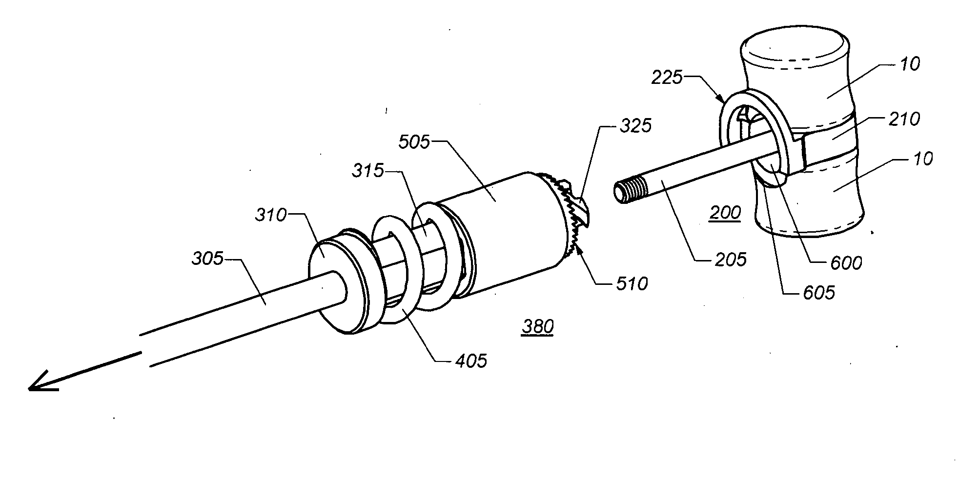
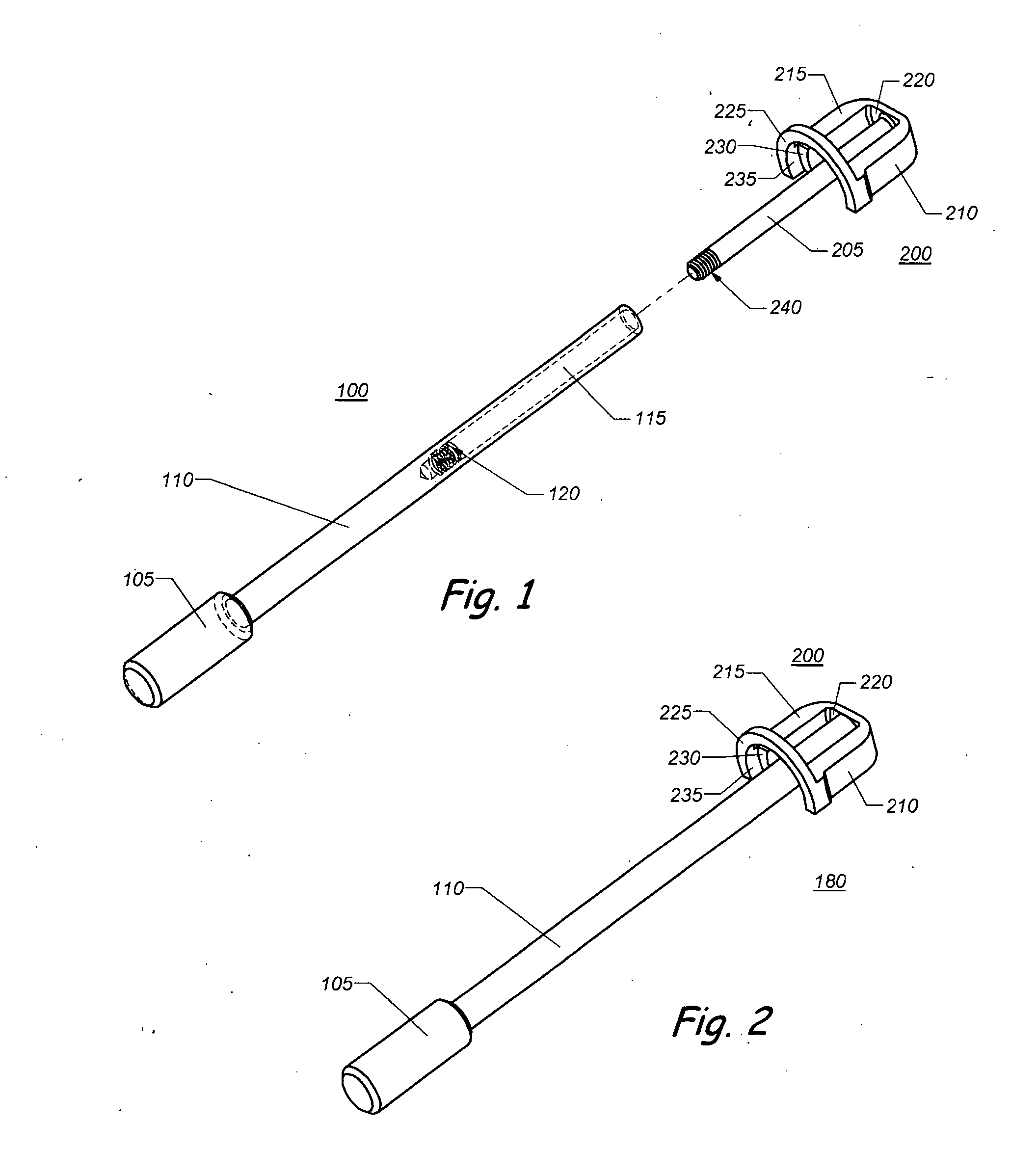
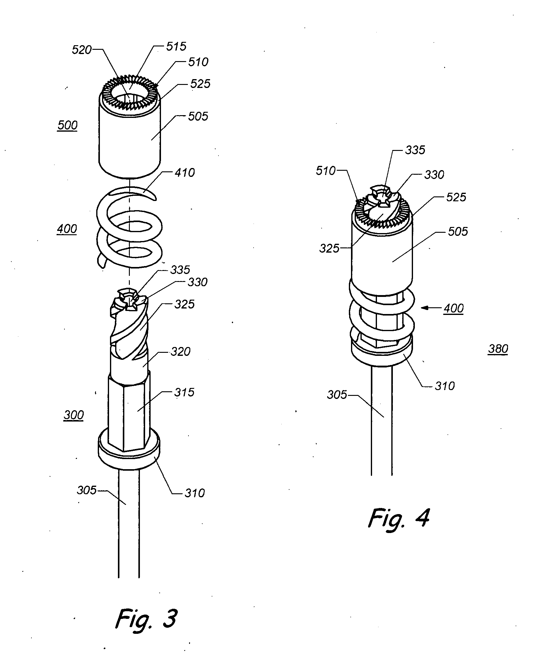
[0007] The present invention is directed to an apparatus and method for use in spinal surgery for creating a space of selected shape and dimensions across the disc space between two adjacent vertebrae of the spine with a guided mill. The present invention comprises instrumentation and a surgical method of preparing vertebral endplates for the procedure, be it fusion or non-fusion, and specifically the creation of a space of a known shape and dimensions. The foregoing is achieved by the use of a mill which is guided by a novel guide mechanism. The instrumentation of the present invention allows for the safe, controlled and protected preparation of the disc space to the optimal depth and width. The present invention allows for the maximum stability of the graft / implant, as well as the construct, by providing for the greatest possible interface surface area and congruency between the graft / implant and each of the adjacent vertebrae.
[0008] It is an object of the present invention to provide for a surgical method and instrument means for performing interbody spinal fusion or in the alternative of inserting an “artificial disc implant” for the purpose of maximizing the width and optimizing the depth of the disc and the bone removed from front to back, or, back to front, from the vertebral endplates adjacent the disc space to be fused or implanted while confining such bone resection safely within the lateral, anterior (front) and posterior (back) limits of the disc space.
[0009] It is another object of the present invention to provide for a surgical method and instrument means for performing interbody spinal fusion or “artificial disc” implantation that provides for the rapid creation of both a known surface contour of each of the vertebral endplates adjacent to a disc space as well as a known and reproducible shape of the fusion or implantation site itself.
[0010] It is another object of the present invention to provide for a surgical method and instrument means for performing interbody spinal fusion that allows for the utilization of a larger interbody spinal fusion implant(s) than was possible with the prior art, such an implant having the capacity for providing increased amounts of osteogenic material, increased surface area, increased area of contact, increased stability and the ability to provide for greater support through the fusion or bone ingrowth area.

Problems solved by technology

However, this can leave gaps between the bones and the implant resulting in sub-optimal results.

Method used


Image

  • Apparatus and method of shaping an intervertebral space
  • Apparatus and method of shaping an intervertebral space
  • Apparatus and method of shaping an intervertebral space

Examples


embodiment 800

[0051]FIG. 14 shows an alternative guide mechanism embodiment 800 which incorporates an angular intervertebral portion 805 with an angle A which is meant to match a lordotic angle in disc space 20. In addition, alternative guide mechanism 800 incorporates a tapered bore 820 to accept a tapered mill. An alternative depth stop 810 with slots 815 is meant to allow either attachment to adjacent vertebrae 10 with screws or pins or to slide over a Caspar type distractor or other distractor means.

embodiment 900

[0052]FIGS. 15a &15b show a further alternative guide mechanism embodiment 900 which incorporates two elongated guide shafts 925 and 930 for guiding mill 300 to create two circular recesses for placement of two adjacent implants. More than two elongated guide shafts can be implemented for implantation of more than two implants. The orientation of elongated guide shafts 925 and 930 may be varied to create circular recesses and / or circular shoulders with differing orientations. FIG. 15b is a back view of further alternative guide mechanism embodiment 900 to illustrate attachment means 920 which may be in the form of spikes for firm attachment to adjacent vertebrae 10.

[0053]FIGS. 16a &16b illustrate implantation of a disc replacement prosthesis 1000 into disc space 20. Disc replacement prosthesis 1000 incorporates tabs 1005&1010 which fit into circular shoulders 605. FIG. 16a shows disc replacement prosthesis 1000 before implantation and FIG. 16b shows the completed implantation.

[0054...


PUM


Abstract

An apparatus and method for creating a space of defined length, height, width and shape with a guided mill in preparation for receiving a spinal implant or graft of known size and configuration is disclosed.

Description

CROSS-REFERENCE TO RELATED PATENT APPLICATION [0001] This application claims priority to and the benefit of, pursuant to 35 U.S.C. §119(e), U.S. provisional patent application Ser. No. 60 / 777,271, filed Feb. 28, 2006, entitled “Apparatus and method of shaping an intervertebral space” by Jeffrey David Gordon and John K Song and is incorporated herein by reference in its entirety.FIELD OF THE INVENTION [0002] The present invention generally relates to a surgical device for creating a cavity between or within bones of the human body. BACKGROUND OF THE INVENTION [0003] Spinal surgery is a rapidly expanding field and interbody grafts (grafts placed between two adjacent vertebrae) are an important means of supporting the space between the vertebrae for purposes of fusion or motion preservation. [0004] To implant an interbody graft, whether in the cervical, thoracic, or lumbar spine, an anterior approach to the spine is often performed. The space where the implant (e.g. cage, spacer, verte...

Claims


Application Information

Patent Timeline
IPC IPC(8): A61F2/44A61B17/17A61B17/16
CPCA61B17/1617A61B17/1671A61F2/446A61B2019/304A61B17/1757A61B2090/034
Inventor GORDON, JEFFREY DAVIDSONG, JOHN K.
Owner VERMILLION TECH
Learn More