Monitor system, and monitor device and data collecting device therefor

a monitoring system and monitor technology, applied in the direction of digital computer details, program control, instruments, etc., can solve the problems of increasing the cycle time, even unexpected operation errors, and the limited manner of using the monitoring devi

Active Publication Date: 2007-08-30
ORMON CORP
View PDF4 Cites 9 Cited by
  • Summary
  • Abstract
  • Description
  • Claims
  • Application Information

AI Technical Summary

Benefits of technology

[0020] With a data collecting unit thus structured according to this invention, virtual variable data based on preliminarily set calculation formulas and the real variable data collected from the programmable controller can be obtained on the side of the data collecting unit. Desired data can be monitored by transmitting these obtained data to the side of th

Problems solved by technology

This is because the newly added calculation may cause an increase in the cycle time and even an unexpected operational error.
As

Method used


Image

  • Monitor system, and monitor device and data collecting device therefor
  • Monitor system, and monitor device and data collecting device therefor
  • Monitor system, and monitor device and data collecting device therefor

Examples


first embodiment

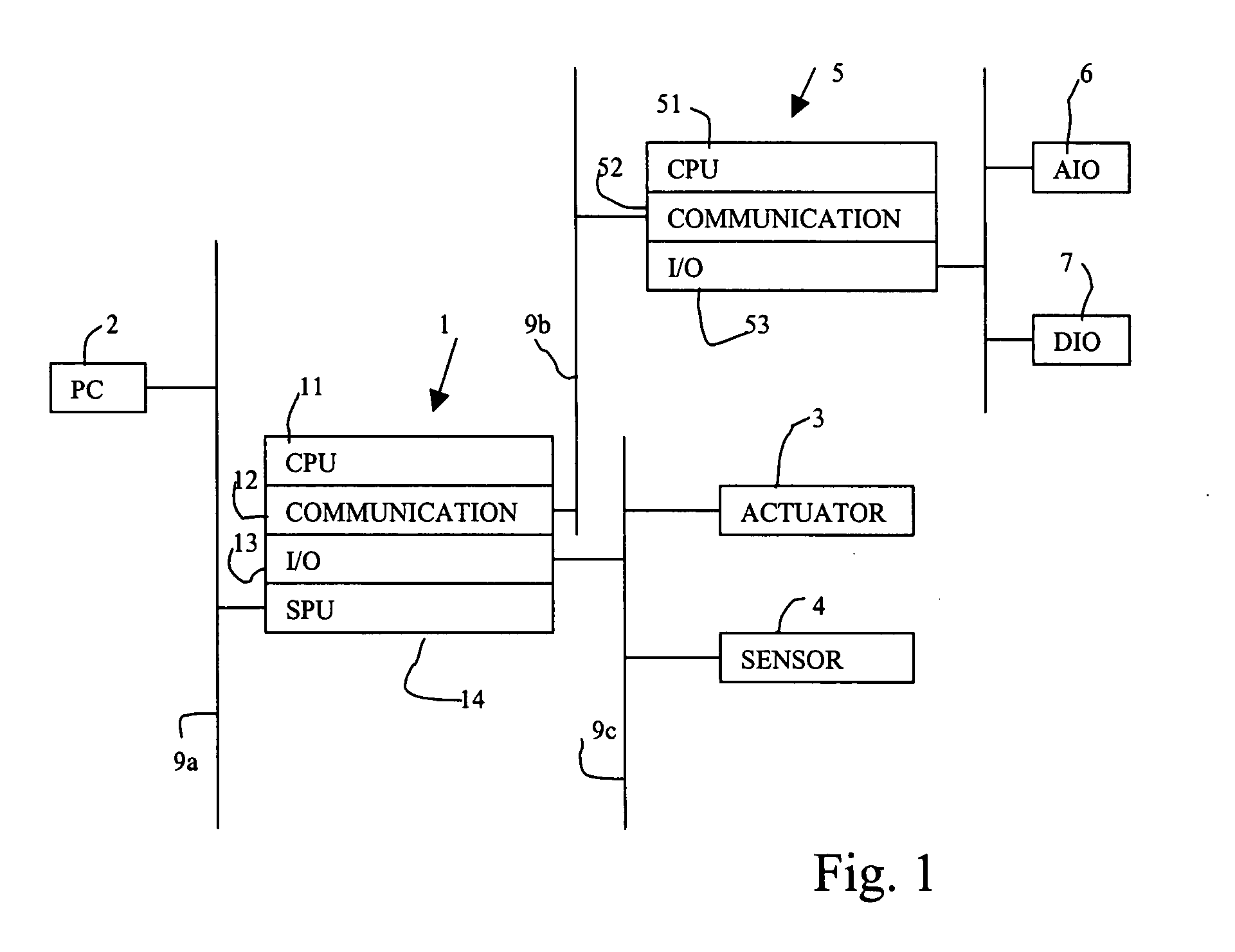
[0077] As in the case of the invention described above, the data collecting unit 14 serves to read out all or specified variable data from the memory of the CPU unit 11 of the PLC 1 through the bus and to store them in the memory within the data collecting unit 14. The data collecting unit 14 is also adapted to communicate with the PC 2 such that the collected data are read out by the PC 2. Based on the data thus obtained, the PC 2 serves to display as shown in FIG. 9 the time series of changes at pulse array waveforms or analog waveforms in a plurality of lines corresponding to each of the variable data. Thus, the user can visually monitor the I / O data handled by the PLC 1 and analog data of various kinds through the screen of the image display device.

[0078]FIG. 10 shows the functional structure of this data collecting unit 14. As shown, this data collecting unit 14 is comprised of a PLC interface 14a, a sampling part 14b, a calculating part 14c, a memory 14d, a file managing part ...

third embodiment

[0103] According to the invention, the calculation processes for obtaining virtual variables are carried out both on the side of the data collecting unit and on the side of the monitoring device. When virtual variables are set and registered according to this embodiment of the invention, there is an additional step of selecting whether a device for carrying out the process of obtaining each virtual variable is provided on the side of the data collecting unit or on the side of the monitoring device. If the side of the data collecting unit is selected, the calculation formulas for obtaining the virtual variables are stored on the side of the data collecting unit. If the side of the monitoring device is selected, they are stored on the side of the monitoring device. In summary, it is structured such that a device other than the CPU unit 11 of the PLC 1 will set and register the calculation formulas for obtaining the virtual variables, collect the real variables necessary for obtaining ...


PUM


Abstract

A monitor system is formed with a programmable controller for executing a user program, a data collecting unit connected to the programmable controller for collecting variable data of the programmable controller and a monitor device connected to the data collecting unit through a communication line. The functions of the system include that of storing a preliminarily defined virtual variable apart from the user program of the programmable controller and from the variable data of the programmable controller and a calculation formula using one or more real variables for obtaining the virtual variable, that of collecting real variable data in the stored calculation formula and any other real variables from the programmable controller, that of carrying out a calculation according to the stored calculation formula based on the collected real variable data, and that of displaying correspondence of the collected real variables and the result of the calculation as waveforms on a display device. Some of these functions are carried out by the data collecting unit, the rest being carried out by the monitor device.

Description

[0001] This application claims priority on Japanese Patent Applications 2006-037259 and 2006-037293 filed Feb. 14, 2006. BACKGROUND OF THE INVENTION [0002] This invention relates to devices for collecting a plurality of control data from a programmable controller memory by means of a data collecting unit connected to the programmable controller through a bus, outputting these collected data to a monitor device such as an image display, and causing these control data to be displayed sequentially in time and monitored by the monitor device. [0003] A programmable controller (PLC) is formed by using a bus to connect a CPU unit for a control, a communication unit for communicating with the exterior and an I / O unit for connecting to sensors. The CPU unit contains a microprocessor and a user memory that stores user programs preliminarily created according to the details of the control. The I / O refresh process, the user program execution process and the peripheral service process are cyclic...

Claims


Application Information

Patent Timeline
IPC IPC(8): G06F17/10G06F17/50
CPCG05B19/052G05B19/058G05B2219/14088G05B2219/14003G05B2219/14006G05B2219/14002
Inventor JINZENJI, TADAMITSUFUJII, MASAAKINISHIYAMA, YOSHIHIDE
Owner ORMON CORP
Why Eureka
Try Eureka