Thermoelectric cooling apparatus

Inactive Publication Date: 2007-09-06
CHANNEL WELL TECH
View PDF3 Cites 6 Cited by
  • Summary
  • Abstract
  • Description
  • Claims
  • Application Information

AI Technical Summary

Benefits of technology

[0014]The thermoelectric cooling apparatus according to the present invention can suck the air outside the electronic device and cool the air with the thermoelectric chip cooling module. In addition, using the wind guide conducts the air to directly reduce the operating temperature of the high power integrated circuits, for example, a CPU

Problems solved by technology

Therefore, the electric circuit layouts of semiconductors have become more complicated and more sophisticated.
Complicated and sophisticated semiconductors have higher power consumption, which results in an increase in the operating temperature thereof.
The high operating temperature can cause instabilities in a working system.
Furthermore, if the operating temperature is too high, the perfor

Method used


Image

  • Thermoelectric cooling apparatus
  • Thermoelectric cooling apparatus
  • Thermoelectric cooling apparatus

Examples


Example

[0020]The following description is of the best presently contemplated mode of carrying out the present invention. This description is not to be taken in a limiting sense but is made merely for the purpose of describing the general principles of the invention. The scope of the invention should be determined by referencing the appended claims.

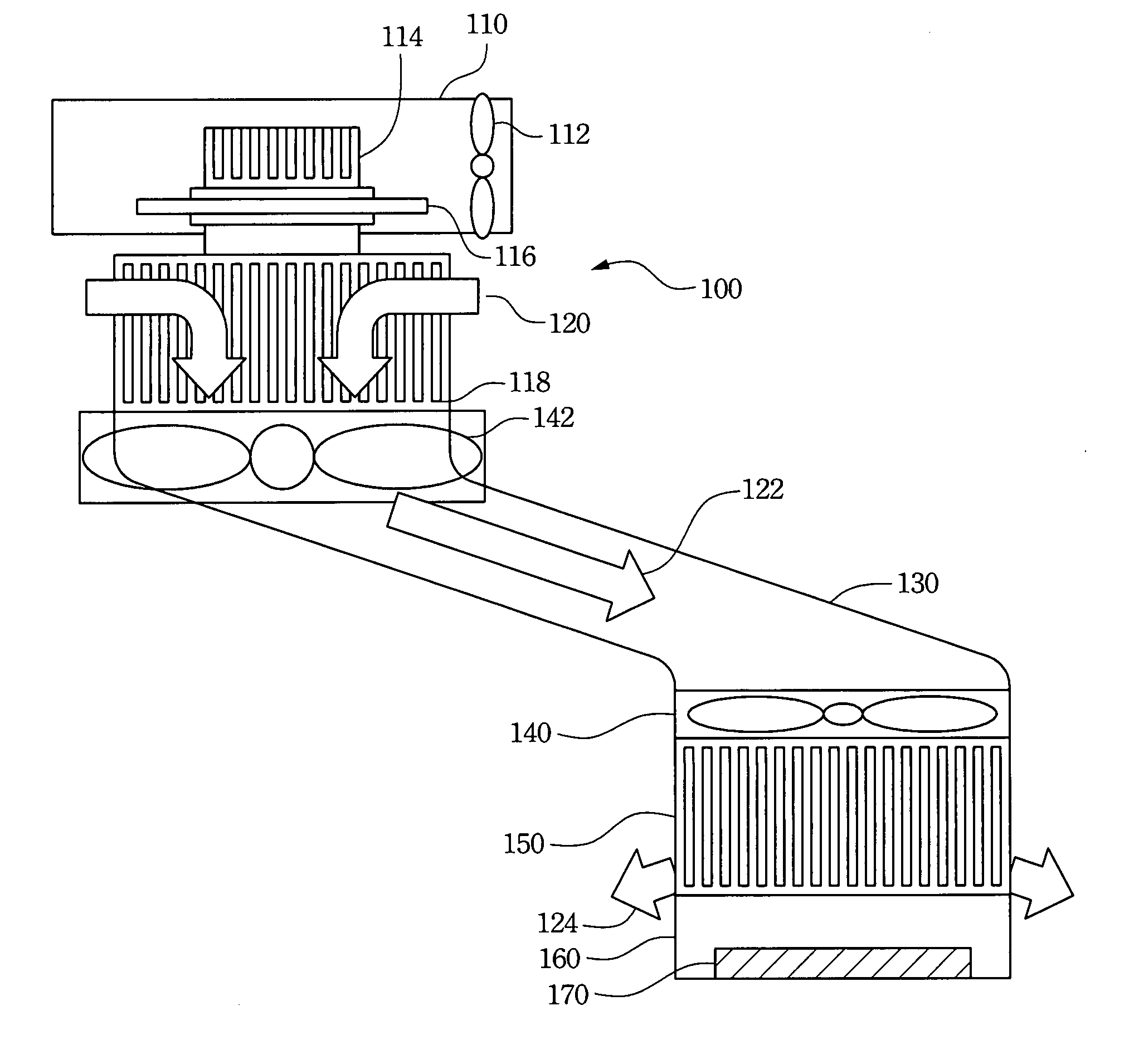
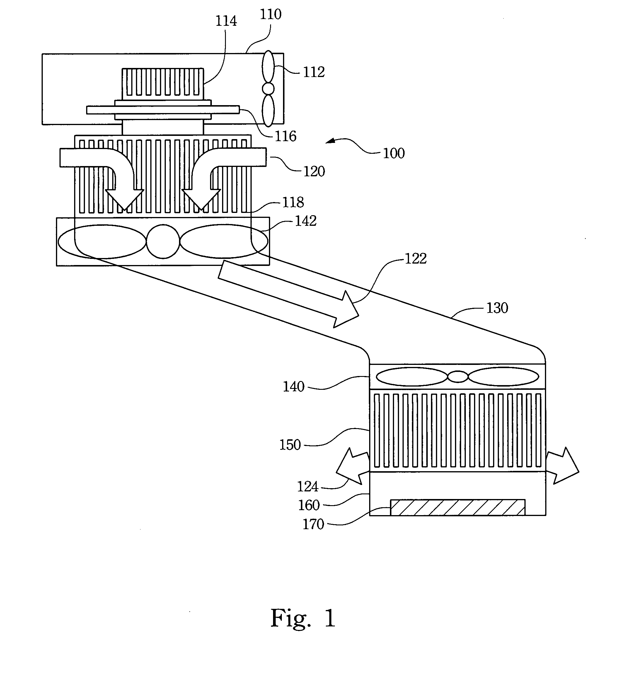
[0021]Refer to FIG. 1. FIG. 1 is a schematic view of a thermoelectric cooling apparatus according to the present invention. The thermoelectric cooling apparatus 100 includes a fan 112, heat-dissipating fins 114, a thermoelectric chip cooling module 116, cooling fins 118 and a wind guide 130. The fan 112, heat-dissipating fins 114 and thermoelectric chip cooling module 116 are disposed inside the heat-dissipating barrel 110. The cooling fins 118 are coupled to the thermoelectric chip cooling module 116 to cool air 120 sucked from the outside so as to form cooling air 122. The cooling air 122 is directly blown to a heat source 170, such as a CPU, a...


PUM


Abstract

A thermoelectric cooling apparatus is described. The thermoelectric cooling apparatus includes a heat-dissipating barrel, a wind guide, cooling fins, and a guiding fan. The heat-dissipating barrel further includes a thermoelectric chip cooling module and heat-dissipating fins disposed therein to remove the heat exchanged by the thermoelectric chip cooling module. One end of the wind guide is coupled to a heat source of an electronic device, for example, a CPU or a graphic chip of a computer. Another end of the wind guide is coupled to the cooling fins coupled to the thermoelectric chip cooling module. The guiding fan drives air passing through the cooling fins to reduce a temperature thereof and blowing to the heat source to reduce the operating temperature thereof.

Description

RELATED APPLICATIONS[0001]The present application is based on, and claims priority from, Taiwan Application Serial Number 95203659, filed Mar. 6, 2006, the disclosure of which is hereby incorporated by reference herein in its entirety.FIELD OF THE INVENTION[0002]The present invention generally relates to a thermoelectric cooling apparatus. More particularly, this invention relates to a thermoelectric cooling apparatus for a computer system.BACKGROUND OF THE INVENTION[0003]The information technology and the computer industry are technologically highly developed and the semiconductor manufacturing processes have very advanced requirements. Therefore, the electric circuit layouts of semiconductors have become more complicated and more sophisticated. Complicated and sophisticated semiconductors have higher power consumption, which results in an increase in the operating temperature thereof.[0004]However, semiconductor electronic components are used extensively in computer products, comm...

Claims


Application Information

Patent Timeline
IPC IPC(8): F25B21/02F25D23/12F25B7/00
CPCF25B21/02F25B2321/0251H01L23/38H01L35/30H01L2924/0002H01L2924/00H10N10/13
Inventor PAN, CHUN-WEI
Owner CHANNEL WELL TECH
Why Eureka
Try Eureka