Anti-deformation foot roll combination device for bloom segment and its application method

A technology of combined device and application method, applied in the field of metallurgy, can solve the problems of decreasing the number of continuous casting furnaces, increasing the production cost, reducing the amount of steel passing through the continuous casting machine, and achieving the effect of long service life and non-deformed service life.

Active Publication Date: 2017-06-20
NANJING IRON & STEEL CO LTD
View PDF6 Cites 0 Cited by
  • Summary
  • Abstract
  • Description
  • Claims
  • Application Information

AI Technical Summary

Problems solved by technology

After the slab leaves the crystallizer, it enters the fan section (that is, the first roller entering the fan section—foot roll assembly), the slab first touches the foot roll, and the foot roll clings to the surface of the slab to play a guiding role. When the slab enters the fan-shaped section, the surface temperature is extremely high (between 1000-1200°C). In this area, the water nozzle in the fan-shaped section cools the casting slab and also unilaterally cools the upper part of the foot roll assembly. One rotation, the temperature changes greatly, and the foot roll assembly is easily deformed due to the long assembly of the foot roll, resulting in quality defects such as scratches and indentations on the surface of the slab
If scratches or indentations are serious, it will cause the continuous casting single line to stop pouring or the whole stop to replace the foot roll, resulting in increased production costs, decreased number of continuous casting furnaces, reduced steel passing capacity of the continuous casting machine, billet mold repair, and lower grades, etc. Negative effects of the series

Method used


Image

  • Anti-deformation foot roll combination device for bloom segment and its application method
  • Anti-deformation foot roll combination device for bloom segment and its application method
  • Anti-deformation foot roll combination device for bloom segment and its application method

Examples


Embodiment 1

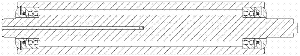
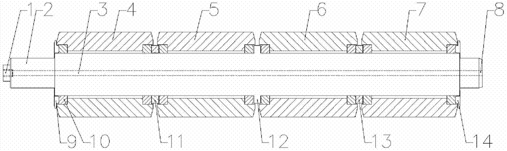
[0025] This embodiment provides an anti-deformation foot-roll combination device for a sector of a bloom, the structure of which is as follows: figure 2 As shown, including the central axis 2, a through hole 3 is provided at both ends of the entire central axis 2 with the center line of the central axis 2 as the center. The through hole 3 includes a water inlet 1 and a water outlet 8, and the water inlet 1 is provided with a For the screw hole of the water pipe, the end of the central axis 2 near the water inlet 1 is provided with a first end cover 9, and the end of the central axis 2 near the water outlet 8 is provided with a second end cover 14, and the first end cover The first foot roller 4, the second foot roller 5, the third foot roller 6 and the fourth foot roller 7 are sequentially nested between the plate 9 and the second end cover plate 14, and the first foot roller 4 and the second foot roller A first positioning ring 11 is installed at the junction of 5, a collar ...

Embodiment 2

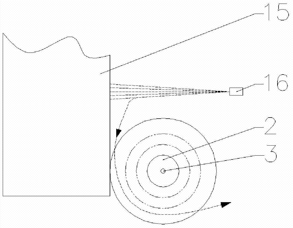
[0029] This embodiment provides an invention and also provides an application method of the anti-deformation foot-roller combination device of the sector of the bloom, such as image 3 As shown, the specific method is as follows:

[0030] When the slab leaves the crystallizer, it enters the foot roll combination device, and the four small foot rolls rotate freely through self-lubricating bearings;

[0031] Install the water pipe through the screw hole at the water inlet 1, and pass cold water into the through hole 3 to cool the central shaft 2, and the water in the through hole 3 finally flows out from the water outlet 8;

[0032] Open the secondary cooling water nozzle 16 to carry out secondary cooling to the slab;

[0033] The secondary cooling water is shot vertically at the slab, and part of the water and water vapor pass through the gaps between the four small foot rolls. At the same time, the secondary cooling water contacts the slab and is also vaporized into steam, so...


PUM

PropertyMeasurementUnit
lengthaaaaaaaaaa

Abstract

The invention discloses an anti-deformation foot-roller assembly device for a sector of a bloom. A through hole is arranged at both ends of the entire central axis with the center line of the central axis as the center. The through hole includes a water inlet and a water outlet. The central axis is close to One end of the water inlet is provided with a first end cover plate, the end of the central axis close to the water outlet is provided with a second end cover plate, and the first end cover plate and the second end cover plate are sequentially sleeved with a second end cover plate. One foot roller, the second foot roller, the third foot roller and the fourth foot roller, the first positioning ring is installed at the junction of the first foot roller and the second foot roller, the junction of the second foot roller and the third foot roller A collar is provided, and a second positioning ring is installed at the junction of the third foot roll and the fourth foot roll; the invention also discloses an application method of the anti-deformation foot roll combination device of the sector of the bloom; When just out of the crystallizer, it acts as a guide for the cast slab, and the device of the invention can ensure that the cast slab can be smoothly introduced into the fan section during the continuous casting process, and the cast slab will not cause scratches and indentations.

Description

technical field [0001] The invention belongs to the technical field of metallurgy, in particular to an anti-deformation foot-roll combination device for a sector of a bloom and an application method thereof. Background technique [0002] At present, during the continuous casting process of the continuous casting machine, because the foot roll device works under extremely cold and extremely hot conditions, the foot roll often has bell mouth, bulging belly, and bearing lock, etc., and the shell of the cast slab in this area is relatively thin. This results in scratches and indentations on the surface of the slab. [0003] The foot roll assembly of the sector section of the existing continuous casting machine is mainly composed of a roller with a total length of 471 mm, a shaft with a length of 563 mm and two bearings. The device is lubricated by glycerin to ensure the free rotation of the foot roll, such as figure 1 As shown, the foot roller lubricates the bearings on both si...

Claims


Application Information

Patent Timeline
Patent Type & Authority Patents(China)
IPC IPC(8): B22D11/14
Inventor 夏红杰吴建勇杨奕兵沈玉春
Owner NANJING IRON & STEEL CO LTD
Why Eureka
Try Eureka