Ultrasonic sensor having vibrator mounted on substrate

a technology of ultrasonic vibrator and ultrasonic sensor, which is applied in the direction of sound producing devices, generators/motors, instruments, etc., can solve the problems of attenuation of ultrasonic waves, poor directivity, and higher resonance frequency of the substrate, so as to reduce the rigidity of the substrate, and high directivity and sensitivity

Inactive Publication Date: 2007-09-06
DENSO CORP
View PDF6 Cites 7 Cited by
  • Summary
  • Abstract
  • Description
  • Claims
  • Application Information

AI Technical Summary

Benefits of technology

[0008]The present invention has been made in view of the above-mentioned problem, and an object of the present invention is to provide a compact ultrasonic sensor, in which the resonant frequency is lowered while maintaining a mechanical strength against an impact force.
[0010]The vibrator is connected to a first surface of the substrate with adhesive, and grooves open to a second surface are formed in the substrate to reduce rigidity of the substrate. By reducing the rigidity of the substrate, its resonant frequency is lowered to a level that is desirable to obtain high directivity and sensitivity, without reducing a thickness of the substrate or enlarging its surface area. Since the thickness of the substrate is not reduced, mechanical strength of the substrate against an impact force is not reduced.
[0011]Dead-ended holes may be formed in place of or in addition to the grooves. The grooves may be formed on the first surface on which the vibrator is mounted. In this case, it is preferable not to form the grooves in an area on which the vibrator is connected in order to increase the connecting force of the vibrator to the substrate. The grooves may be formed on both surfaces. The grooves may be formed in a lattice arrangement so that the mechanical strength of the substrate becomes uniform in every direction. Through-holes may be formed in the substrate in place of or in addition to the grooves. Cutout portions may be additionally formed along side surfaces of the substrate to further reduce the rigidity of the substrate. The grooves may be filled with filler having rigidity lower than that of the substrate to prevent foreign particles from entering into the grooves.

Problems solved by technology

However, there has been a problem that a resonant frequency of the substrate 112 becomes higher as its size becomes smaller.
This results in increase in attenuation of the ultrasonic waves and worsening in directivity.

Method used


Image

  • Ultrasonic sensor having vibrator mounted on substrate
  • Ultrasonic sensor having vibrator mounted on substrate
  • Ultrasonic sensor having vibrator mounted on substrate

Examples


Embodiment Construction

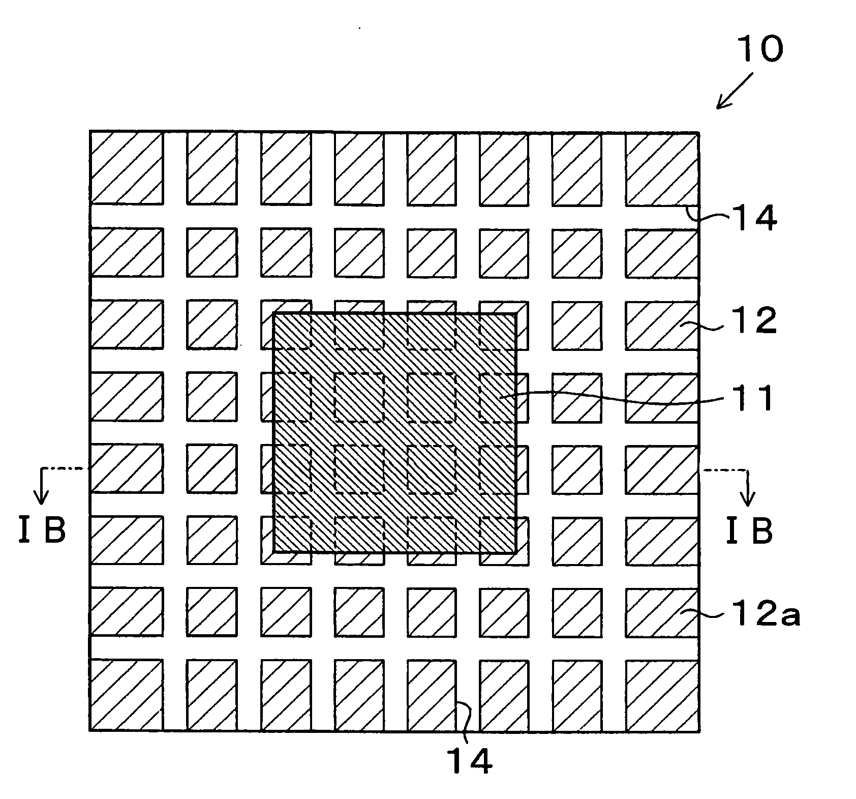
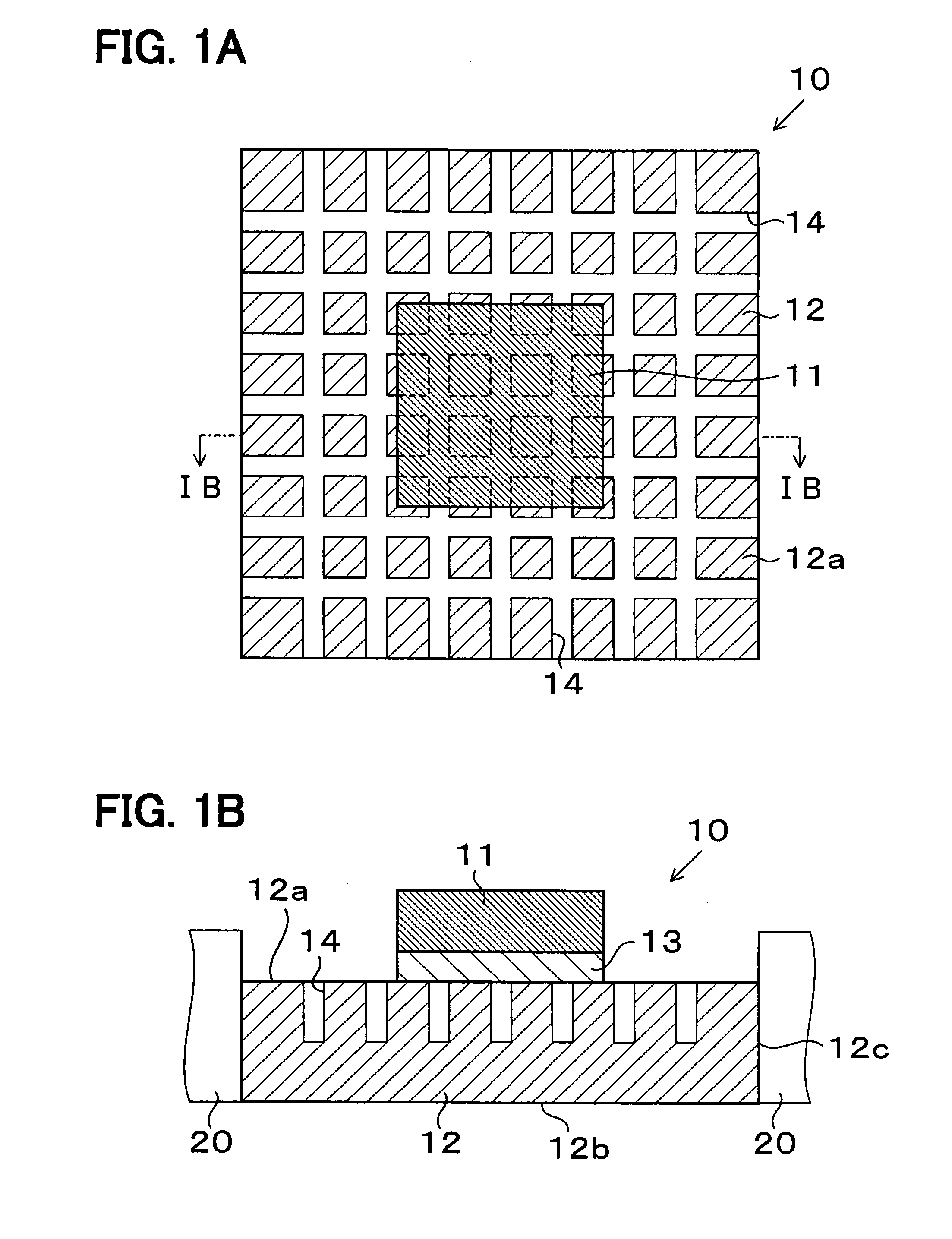
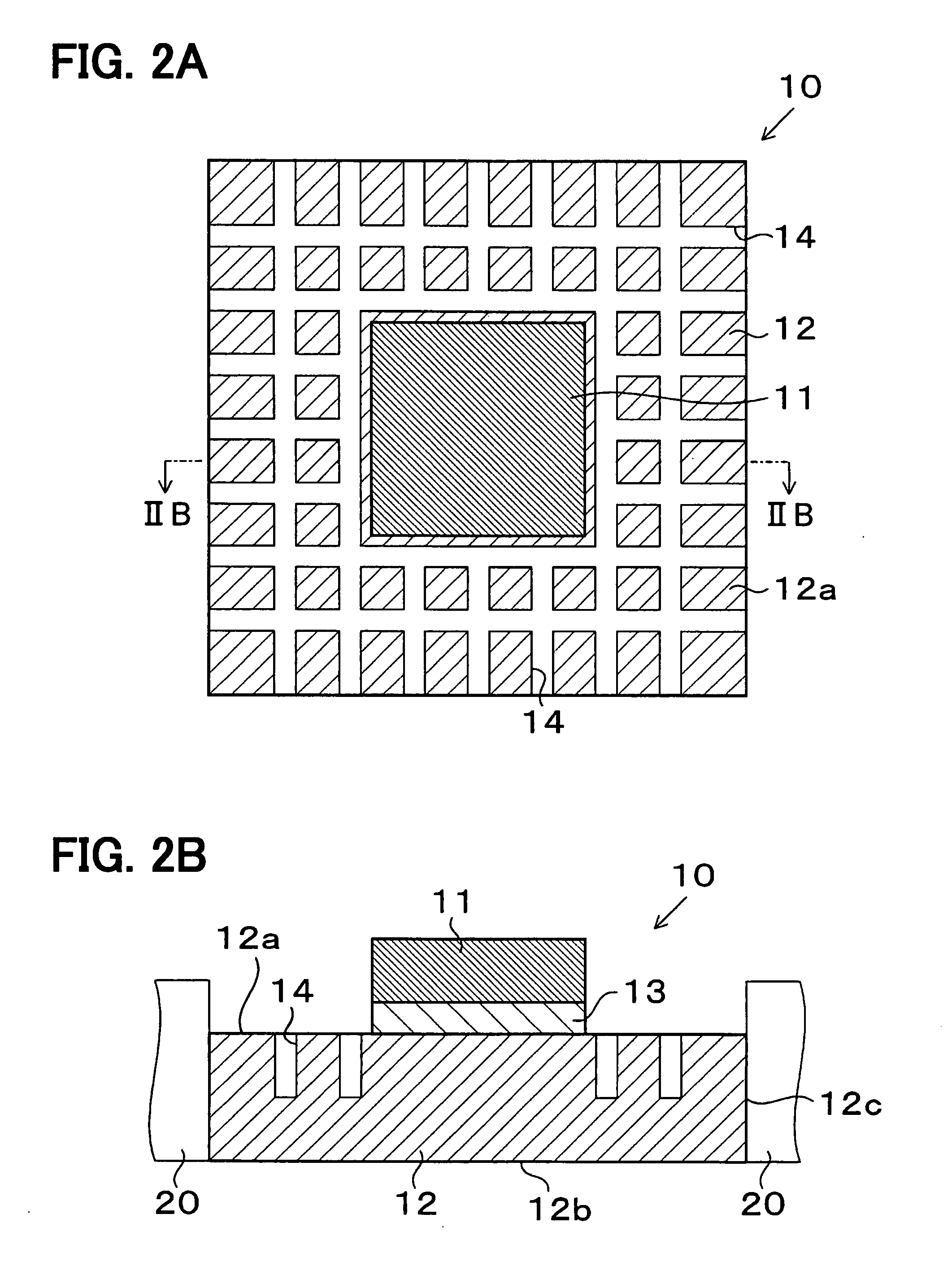
[0023]A preferred embodiment of the present invention will be described with reference to accompanying drawings. As shown in FIGS. 1A and 1B, an ultrasonic sensor 10 includes an ultrasonic vibrator 11 that generates and detects ultrasonic waves and a substrate 12. The ultrasonic vibrator 11 is made of a piezoelectric element such as lead-zirconate-titanate (PZT). The piezoelectric element is sandwiched with a pair of electrodes, forming the ultrasonic vibrator 11 having a thickness of 0.1 mm and a plane area of 1 mm×1 mm. Since PZT has a high piezoelectric coefficient, ultrasonic waves in a high level can be generated, and ultrasonic waves in a low level can be received.

[0024]The substrate 12 is made of a resin material such as engineering plastics and formed in a square plate having a thickness of 0.5 mm and a plane area of 3 mm×3 mm. The resin material can be easily shaped into the substrate 12 at a low cost by molding or machining. The ultrasonic vibrator 11 is connected to a cen...


PUM


Abstract

An ultrasonic sensor composed of a substrate and a piezoelectric vibrator mounted on the substrate is advantageously used as a sensor for detecting a distance to an object located in front of an automotive vehicle. Ultrasonic waves transmitted from the sensor are reflected by the object, and the reflected waves are received by the sensor. Based on the reflected waves, the distance from the vehicle to the object is calculated. To reduce rigidity and thereby to lower a resonant frequency of the substrate to a desirable level, grooves are formed in the substrate. A thickness of the substrate is not reduced to maintain its mechanical strength against an impact force. A resonant frequency which is desirable to realize a sufficiently high directivity and sensitivity is obtained in this manner without enlarging a size of the ultrasonic sensor.

Description

CROSS-REFERENCE TO RELATED APPLICATION[0001]This application is based upon and claims benefit of priority of Japanese Patent Application No. 2006-59413 filed on Mar. 6, 2006, the content of which is incorporated herein by reference.BACKGROUND OF THE INVENTION[0002]1. Field of the Invention[0003]The present invention relates to an ultrasonic sensor having an ultrasonic vibrator mounted on a substrate.[0004]2. Description of Related Art[0005]An ultrasonic sensor having a piezoelectric vibrator mounted on a substrate made of such as a metallic material or a resin material has been known hitherto. The ultrasonic sensor is mounted on an automotive vehicle, and ultrasonic waves are emitted from the ultrasonic sensor toward objects in front of or around the vehicle. The objects are detected based on the ultrasonic waves reflected by the objects and received by the ultrasonic sensor. A distance to the objects and two-dimensional or three-dimensional shapes of the objects are detected in thi...

Claims


Application Information

Patent Timeline
Patent Type & Authority Applications(United States)
IPC IPC(8): G01H11/00
CPCG10K9/122
Inventor WATANABE, KAZUAKIYOSHIDA, TAKAHIKOSUGIURA, MAKIKOENDOH, NOBORUOKUDA, YASUYUKI
Owner DENSO CORP
Why Eureka
Try Eureka