Self presenting electronic shifter

a self-presenting, electronic technology, applied in the direction of mechanical control devices, instruments, anti-theft devices, etc., can solve the problems of inadvertent shifting of the type of shifter mechanism, difficulty in moving between the driver's seat and the front passenger seat, etc., to achieve easy adjustment of the assembly, high quality, and low cost

Inactive Publication Date: 2007-09-06
DURA GLOBAL TECH
View PDF10 Cites 31 Cited by
  • Summary
  • Abstract
  • Description
  • Claims
  • Application Information

AI Technical Summary

Benefits of technology

[0011] From the foregoing disclosure and the following more detailed description of various preferred embodiments it will be apparent to those skilled in the art that the present invention provides a significant advance in the technology and art of motor vehicle shifter mechanisms. Particularly significant in this regard is the potential the invention affords for providing a high quality, reliable, low cost, easily adjusted assembly having reduced package size and pleasing aesthetics. Additional features and advantages of various preferred embodiments will be better understood in view of the detailed description provided below.

Problems solved by technology

This type of shifter mechanism makes it difficult for a person to move between the driver's seat and the front passenger seat as needed in some instances such as when the vehicle is parked near heavy traffic or in a very narrow parking space.
Movement is difficult because the upward extending shift lever becomes an obstruction.
Additionally, this type of shifter mechanism can be inadvertently shifted during movement of the driver or the front passenger.
While these folding gear shift levers may permit stowing of the gear shift levers, they can be complicated and expensive to produce in a manner such that the shift lever does not inadvertently fold during operation of the motor vehicle.
Additionally, these folding gear shift levers cane be cumbersome to operate and are aesthetically unpleasing.

Method used


Image

  • Self presenting electronic shifter
  • Self presenting electronic shifter
  • Self presenting electronic shifter

Examples


Embodiment Construction

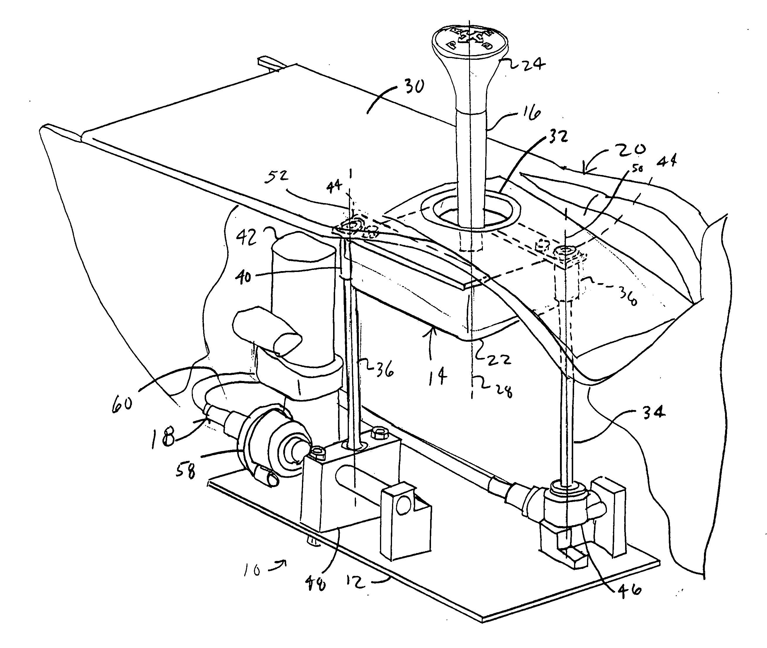
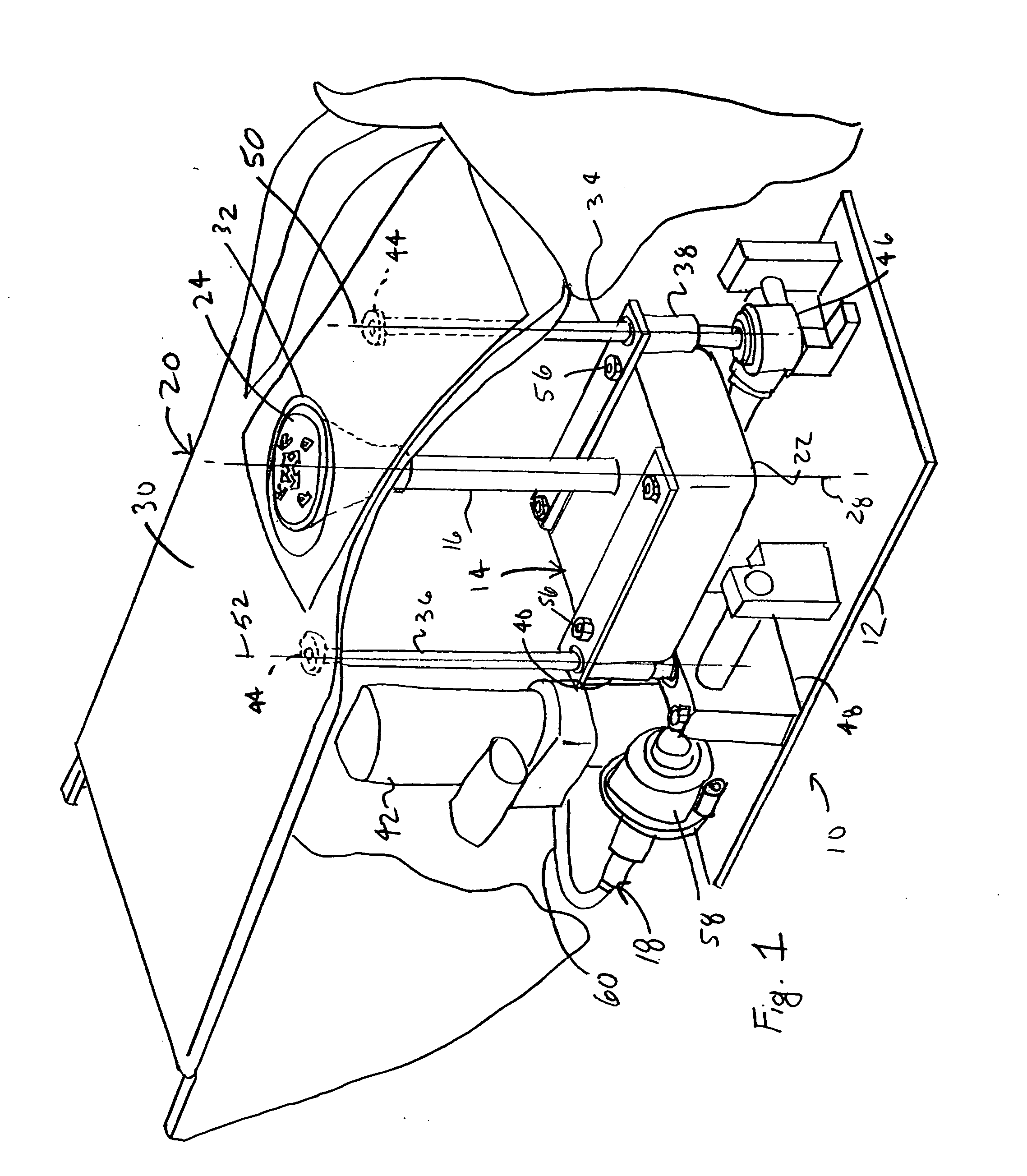
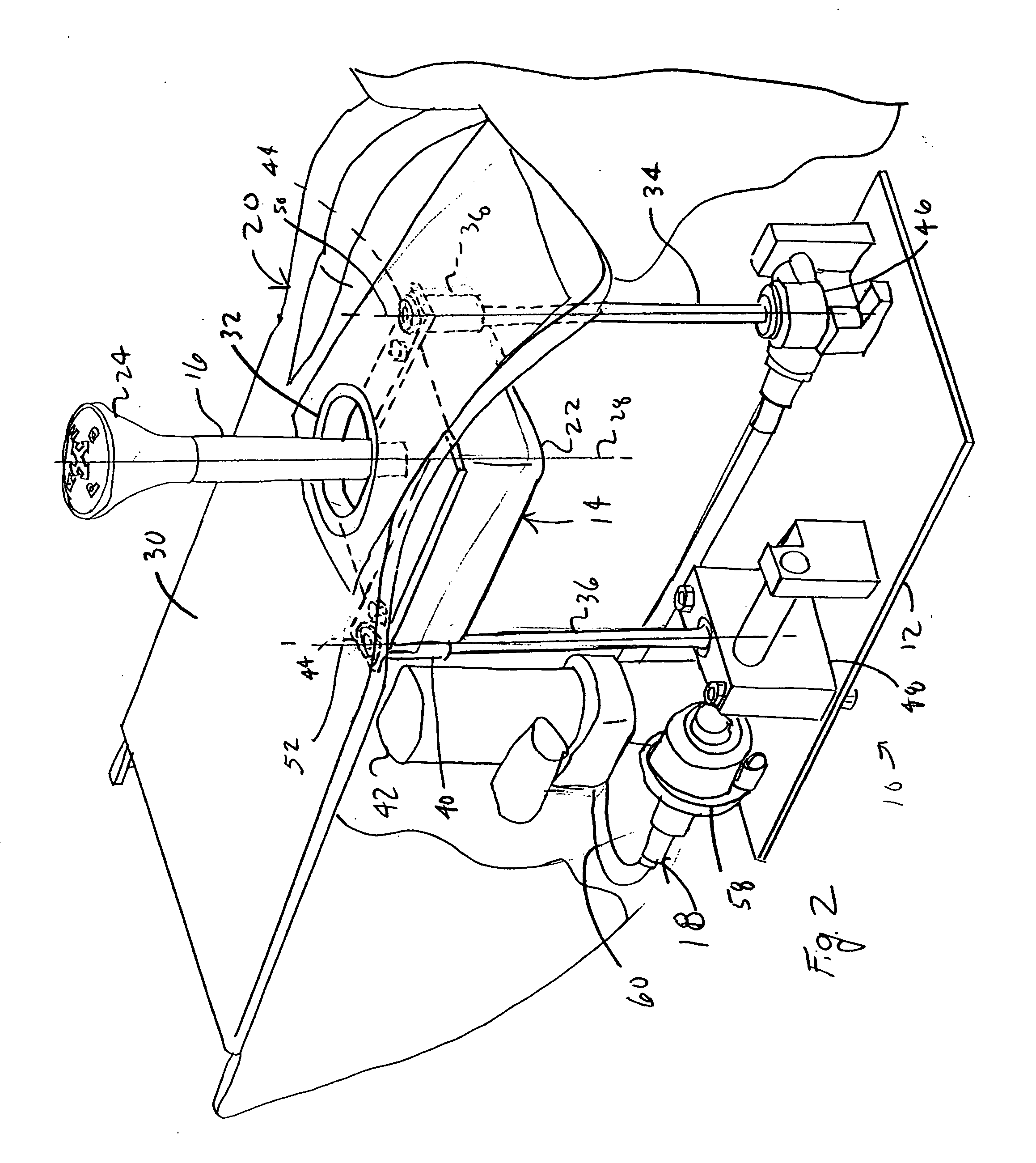
[0017] It will be apparent to those skilled in the art, that is, to those who have knowledge or experience in this area of technology, that many uses and design variations are possible for the improved shifter assembly disclosed herein. The following detailed discussion of various alternative and preferred embodiments will illustrate the general principles of the invention with reference to a shifter mechanism for a motor vehicle such as an automobile, sport utility vehicle (SUV), crossover vehicle, or the like. Other embodiments suitable for other applications will be apparent to those skilled in the art given the benefit of this disclosure.

[0018] Referring now to the drawings, FIGS. 1 to 3 show a shifter assembly 10 according to a preferred embodiment of the present invention. The illustrated shifter assembly 10 includes a frame or base 12, a shifter mechanism 14 including a shift arm or lever 16 pivotable to a plurality of gear positions; and a powered translator or drive system...


PUM


Abstract

A shifter assembly includes an electronic shifter mechanism having a shift lever movable between a plurality of gear positions and an electrically powered drive system operatively connected to the shifter mechanism to selectively move the shifter mechanism between a first location wherein the shifter lever is located substantially within a housing and a second location wherein the shifter lever is located substantially outside the housing. The drive system moves the shifter mechanism along a vertical, linear path substantially parallel to a longitudinal axis of the shift lever such that the shift lever moves through an opening in the housing.

Description

CROSS-REFERENCE TO RELATED APPLICATIONS [0001] Not Applicable STATEMENT REGARDING FEDERALLY SPONSORED RESEARCH [0002] Not Applicable REFERENCE TO MICROFICHE APPENDIX [0003] Not Applicable FIELD OF THE INVENTION [0004] The present invention generally relates to a shifter mechanism for controlling transmissions of motor vehicles and, more particularly, a shifter mechanism that moves between a stowed position and an operating position. BACKGROUND OF THE INVENTION [0005] In a motor vehicle equipped with a transmission, there is typically a shifter mechanism that includes a shift lever pivotable over a series of positions representative of desired transmission gears. The shifter mechanism is connected to the motor vehicle automatic transmission by a suitable mechanical and / or electronic operating linkage to effect actuation of the transmission to the selected gear when the shifter lever is pivoted to the transmission gear's representative position. [0006] Many shifter mechanisms are floo...

Claims


Application Information

Patent Timeline
Patent Type & Authority Applications(United States)
IPC IPC(8): G05G1/04
CPCB60R25/066F16H59/105G05G1/04Y10T74/20612G05G5/06G05G5/28G05G2009/04703G05G5/05
Inventor STRAIT, DANIEL LEESTENZEL, MICHAEL LEE
Owner DURA GLOBAL TECH
Why Eureka
Try Eureka