
Method for forming structured film as molded by tape die

Inactive Publication Date: 2007-09-06
LIN CHING BIN
View PDF9 Cites 37 Cited by
  • Summary
  • Abstract
  • Description
  • Claims
  • Application Information

AI Technical Summary

Problems solved by technology

The costly die roller should always be replaced with a new one, thereby increasing the production cost.

Method used


Image

  • Method for forming structured film as molded by tape die
  • Method for forming structured film as molded by tape die
  • Method for forming structured film as molded by tape die

Examples


Embodiment Construction

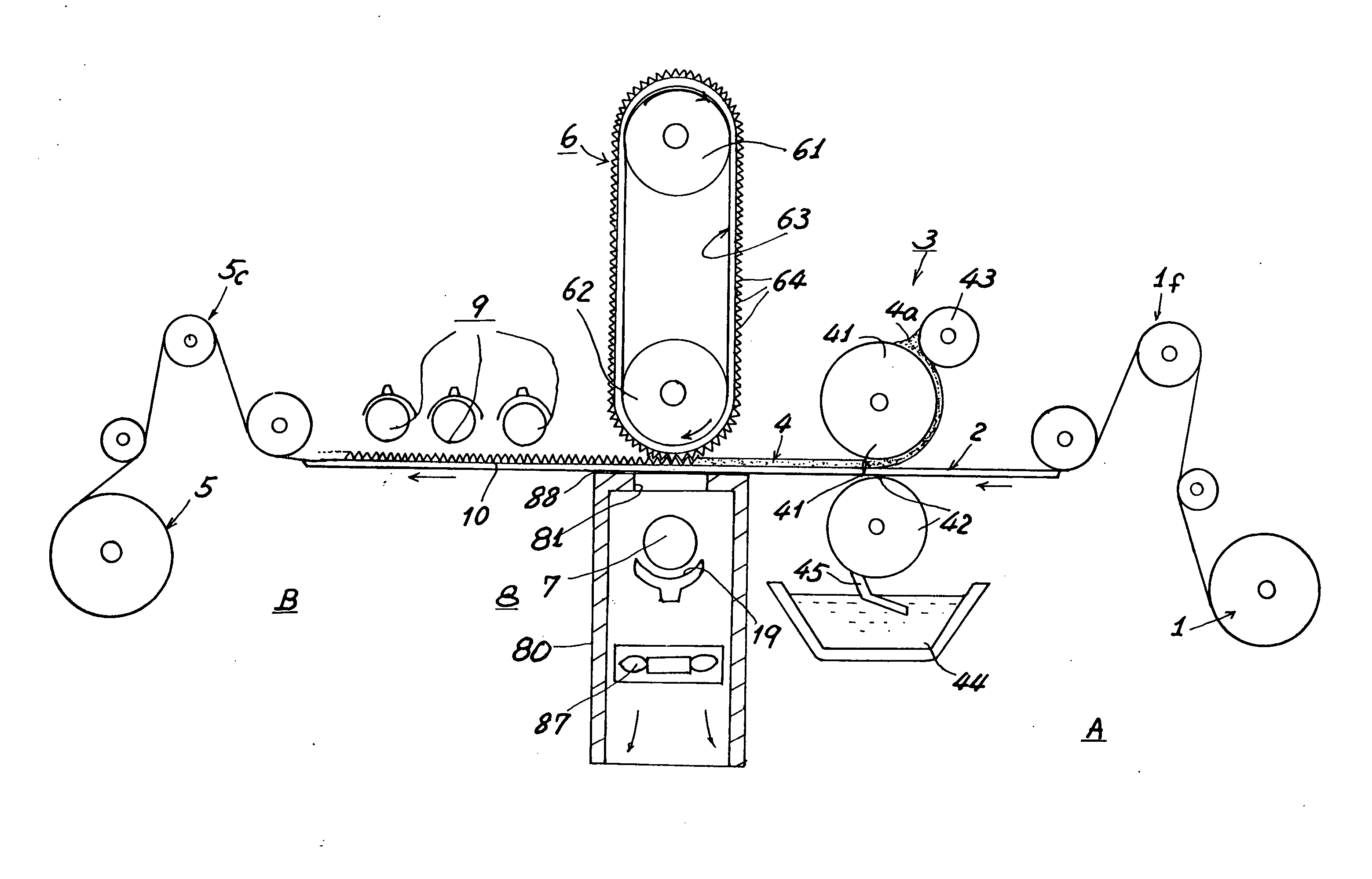
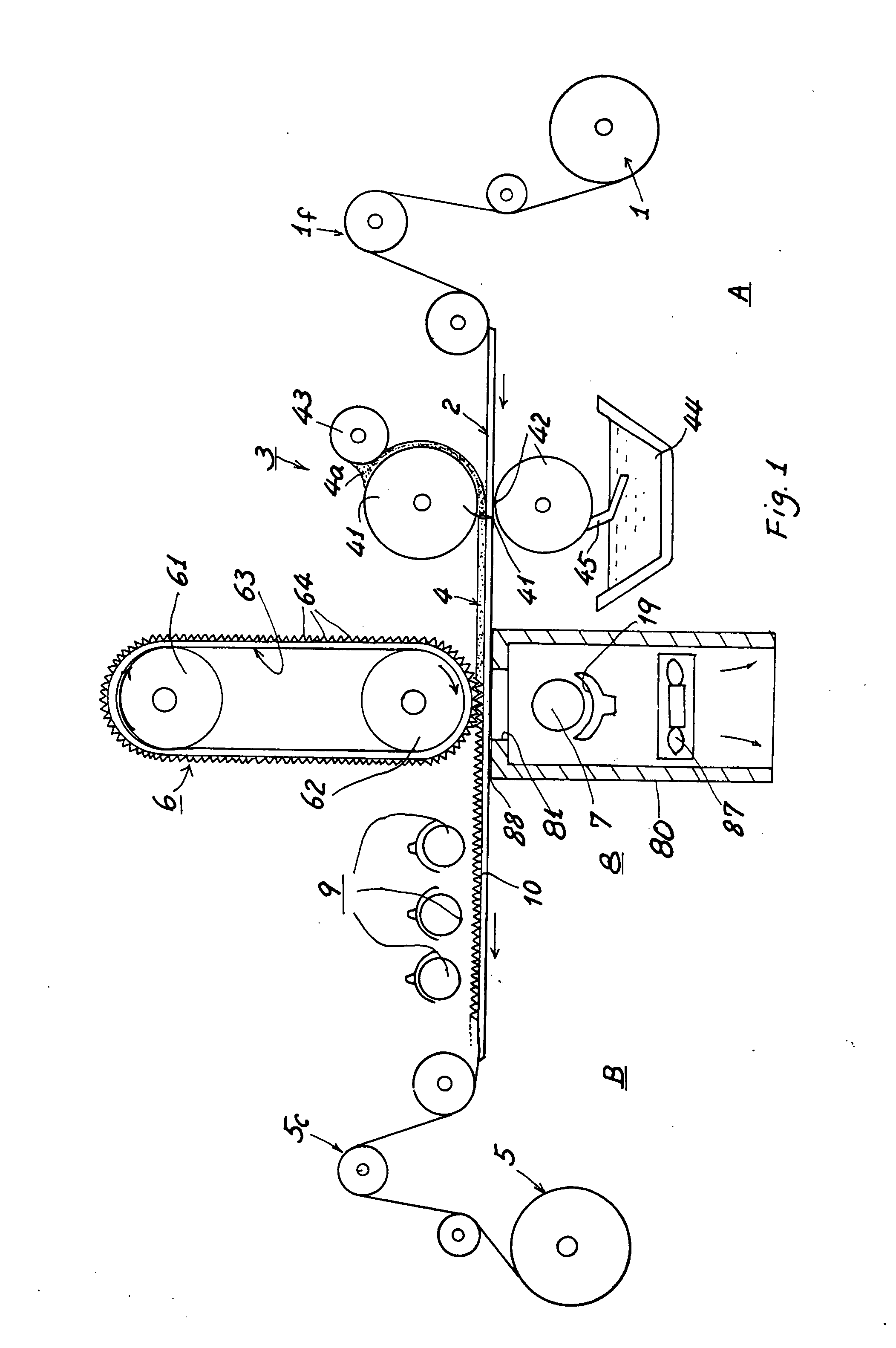
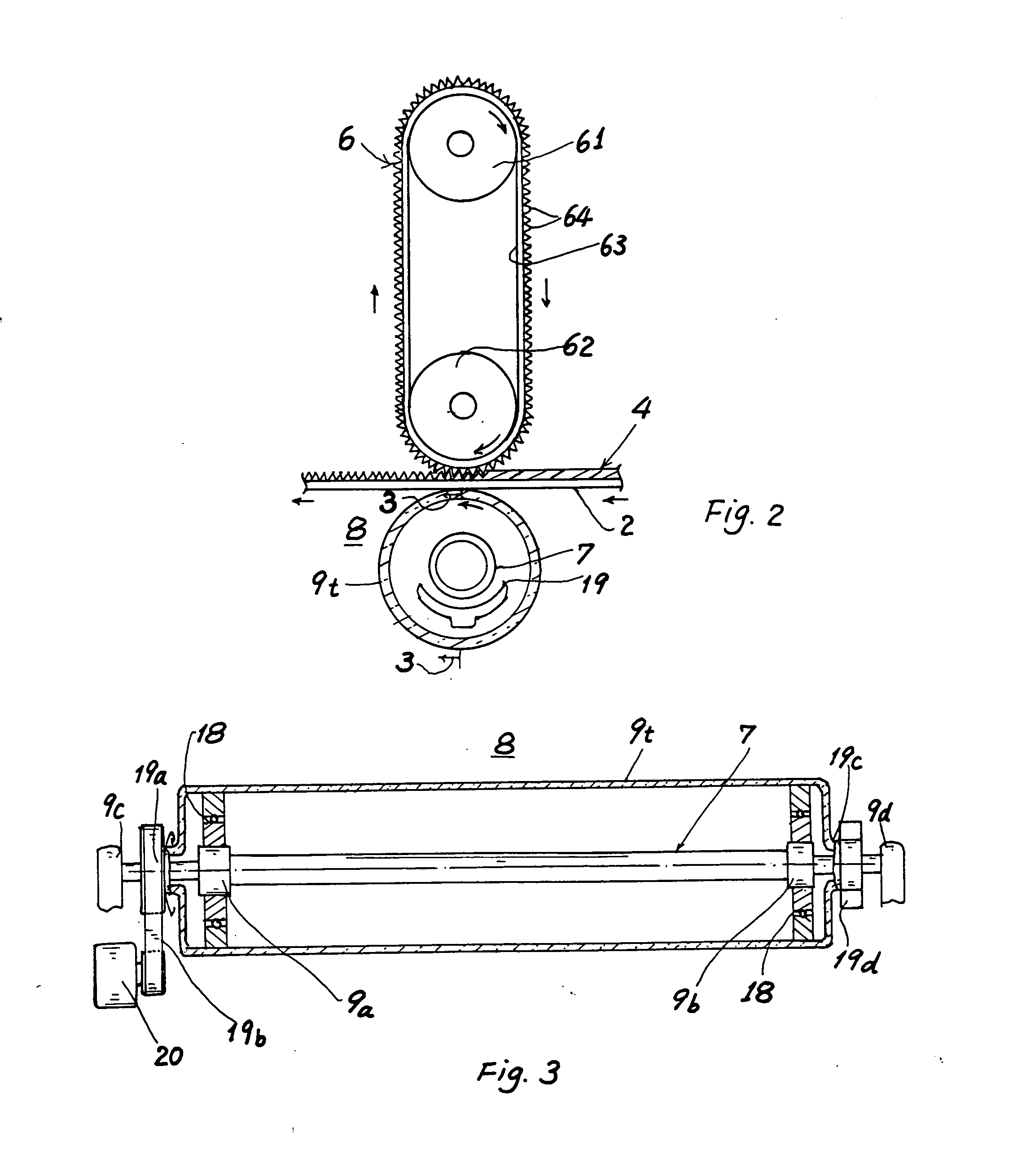
[0014] A method for forming structured or micro-structured film of the present invention comprises the steps of: [0015] A. Coating a photocuring or heat-curing adhesive resin layer on a substrate layer; [0016] B. Molding or forming or imprinting a structured (or micro-structured) pattern including prismatic array on said adhesive resin layer by a tape die having said structured pattern preformed on said tape die; and [0017] C. Curing said photocuring or heat-curing adhesive resin layer on said substrate layer to obtain a layered film having said structured pattern formed thereon.

[0018] In accordance with the present invention, the layered film product may include an optical film having prismatic array or other brightness enhancing structured surface (or surfaces) formed on the upper portion of the layered film. So, the present invention may be provided for making optical films to be used in LCD, and other electronic, computer and electric items.

[0019] The tape die includes the str...


PUM

PropertyMeasurementUnit
Thicknessaaaaaaaaaa
Diameteraaaaaaaaaa
Adhesion strengthaaaaaaaaaa

Abstract

A method for forming structured or micro-structured film comprising the steps of: A. Coating a photocuring or heat-curing adhesive resin layer on a substrate layer; B. Molding or forming or imprinting a structured or micro-structured pattern including prismatic array on the adhesive resin layer by a tape die having the structured pattern preformed on the tape die; and C. Curing the photocuring or heat-curing adhesive resin layer on the substrate layer to obtain a layered film having a structured pattern surface. The structured pattern is formed on the tape, rather than on the rotary die or die roller, to prevent from sticking of the adhesive resin on the roller to prolong the service life of the production equipment and also to ensure a reliable film product quality.

Description

BACKGROUND OF THE INVENTION [0001] U.S. Patent Application Publication No. US 2005 / 0134963 A1 disclosed a display including an optical film that has a surface structure, such as a prismatically structured surface for increasing the brightness of the display. The structured surface is bonded to an opposing surface of a second film using a layer of adhesive, by penetrating the structured surface into the adhesive layer to a depth less than a feature height of the structured surface. [0002] A die (1530) of this prior art is provided on a die roller (1532) for forming the structured surface of the optical film. However, partial adhesive may be adhered to the grooves or tips of the die roller to influence the quality of the film product. The costly die roller should always be replaced with a new one, thereby increasing the production cost. [0003] The present inventor has found the drawbacks of the prior art and invented the present method for forming structured film in a more economical ...

Claims


Application Information

Patent Timeline
IPC IPC(8): B29D31/00B05D5/06B05D3/12C08F2/46B29D99/00
CPCB05D1/28B05D1/40B05D3/0254B05D3/067B05D7/04B29C35/02G02B5/045B29C39/148B29C59/046B29C2035/0827B29C2059/023B29D11/00278B29C35/0888B29D7/01G02B5/02B32B27/00
Inventor LIN, CHING-BIN
Owner LIN CHING BIN
Learn More