
Vehicle and method of modification thereof

Inactive Publication Date: 2007-09-06
W H ASPECT
View PDF13 Cites 17 Cited by
  • Summary
  • Abstract
  • Description
  • Claims
  • Application Information

AI Technical Summary

Benefits of technology

[0007] It is therefore an object of the present invention to address one or more of the problems as hereinabove described. It is also an object of the present invention to provide a vehicle and / or method of modifying an existing vehicle so as to afford better access to the side of a vehicle for a disabled person and / or for loading of articles. Furthermore, it would be advantageous to provide a method of modifying a vehicle such that access can be gained from one or either side of the vehicle in addition to allowing most of the seats of the vehicle to remain intact thereby allowing a number of people to be carried in the same vehicle.
[0011] The present invention therefore provides for a vehicle that can easily load articles and / or persons into the interior in an expedient and efficient manner. It will be apparent to one skilled in the art that while the present invention is directed towards assisting access to a vehicle for a disabled person (when usually sitting on a wheelchair), the present invention could equally be used in order to load goods and products (such as those resting on a pallet) into the side of a vehicle such as a van. The door may also be attached to the platform or vehicle body solely. Alternatively, the door may be attached to both the platform and the vehicle body.
[0015] Potentially, any vehicle door may be attached to the platform, although a front door is preferred. When the door is in the closed position, the door may be held to the vehicle by a locking means. Such a locking means may comprise a “soft closed locking mechanism” which is often found in luxury vehicles, whereby a door is pushed onto a spring loaded latch and an electric motor engages a lock (which may in turn be an extension of the latch itself) after the door is on the latch, so as to prevent a car door from being “slammed shut”.
[0017] The door and / or vehicle may also have a continuous or substantially continuous weather strip disposed around the edge of the door when the door is in the second closed position. It will be apparent to one skilled in the art that additional weather strips may also be employed so as to ensure that the vehicle is water tight and to prevent ingress of water from a number of directions (due to vehicle movement etc.). The ramp may comprise two or more portions that extend telescopically (or the portions capable of riding over one another) when the door is moved to, or located in, the first (open) position. The platform may also form part of the interior floor of the vehicle when the door is in the second closed position. If required, two doors from the same side of the vehicle may be attached to the platform and this may allow for multiple wheelchairs to gain entry into the vehicle itself. Should two doors from the same side of the vehicle be attached to the platform, a B-pillar and / or a structural member may be integrally formed or attached between the two doors so as to maintain the structural integrity of the vehicle when the doors are in the second closed position. Furthermore, the B-pillar and / or structural member may positively locate with the chassis or body of the vehicle when the doors are in the second closed position.
[0018] A B-pillar in the context of this invention should be taken to be a structural member which is disposed between the roof and the floor / sill of a vehicle frame and is commonly used as a member for mounting a rear door, housing a locking means and also used as an anchor point for a seat belt. Additionally, such a structural member is also used to provide structural rigidity for the chassis and the vehicle frame.

Problems solved by technology

It will be evident that certain conditions would not permit a person to leave a wheelchair for fear of making their condition worse or causing problems in moving the person from the wheelchair onto a passenger or driver's seat.
Moreover, access is only gained from the rear and therefore the person in the wheelchair needs to be placed on a road and can not be wheeled directly into the vehicle from the pavement.
Furthermore, the removal of a number of seats may not be appropriate if the disabled person is a member of a large family which necessitates a number of people to be transported at the same time.
Additionally, the arrangement requires a disabled person to manoeuvre himself or herself over onto the passenger / driver seat from the wheelchair itself which can often be a difficult and dangerous procedure.

Method used


Image

  • Vehicle and method of modification thereof
  • Vehicle and method of modification thereof

Examples


Embodiment Construction

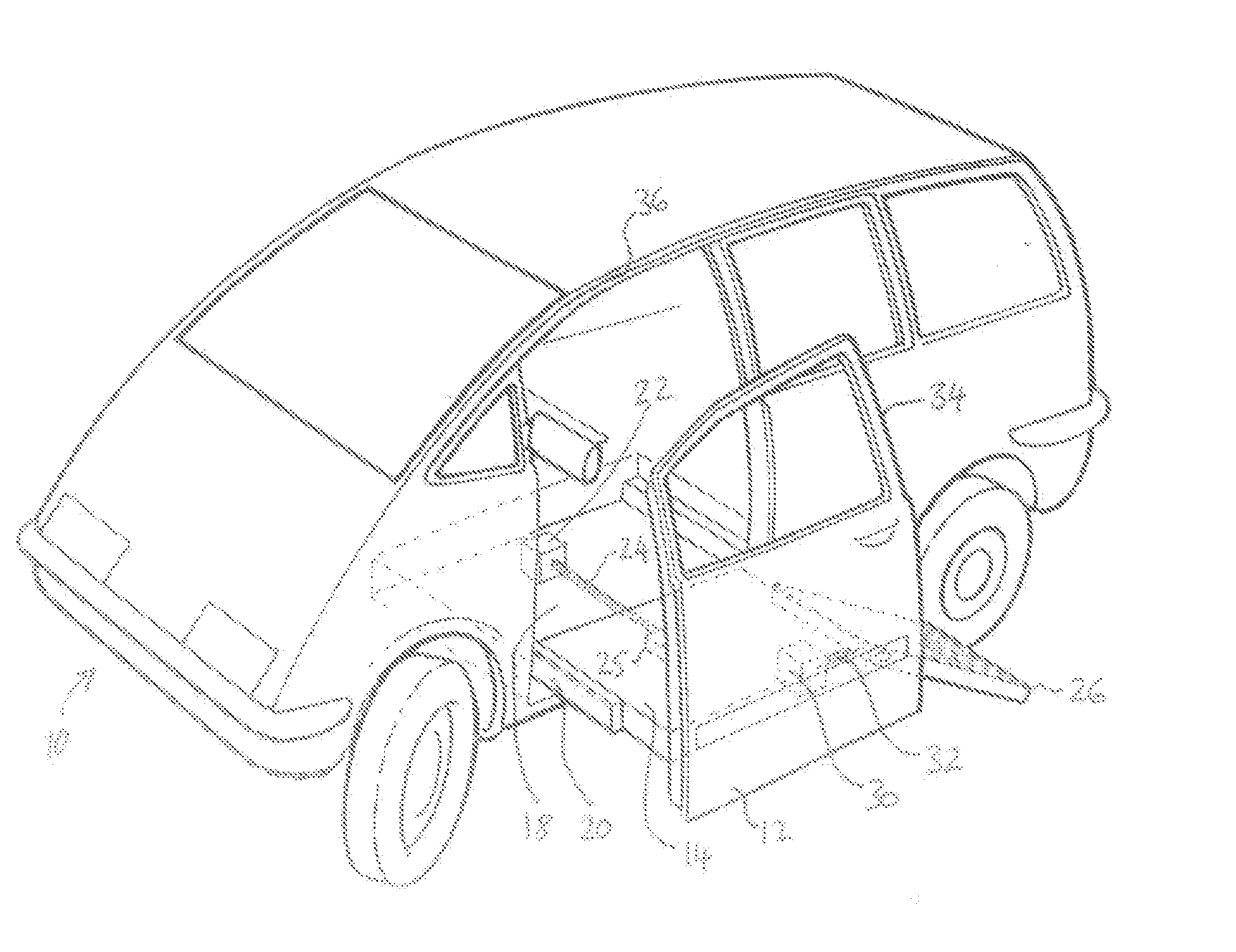
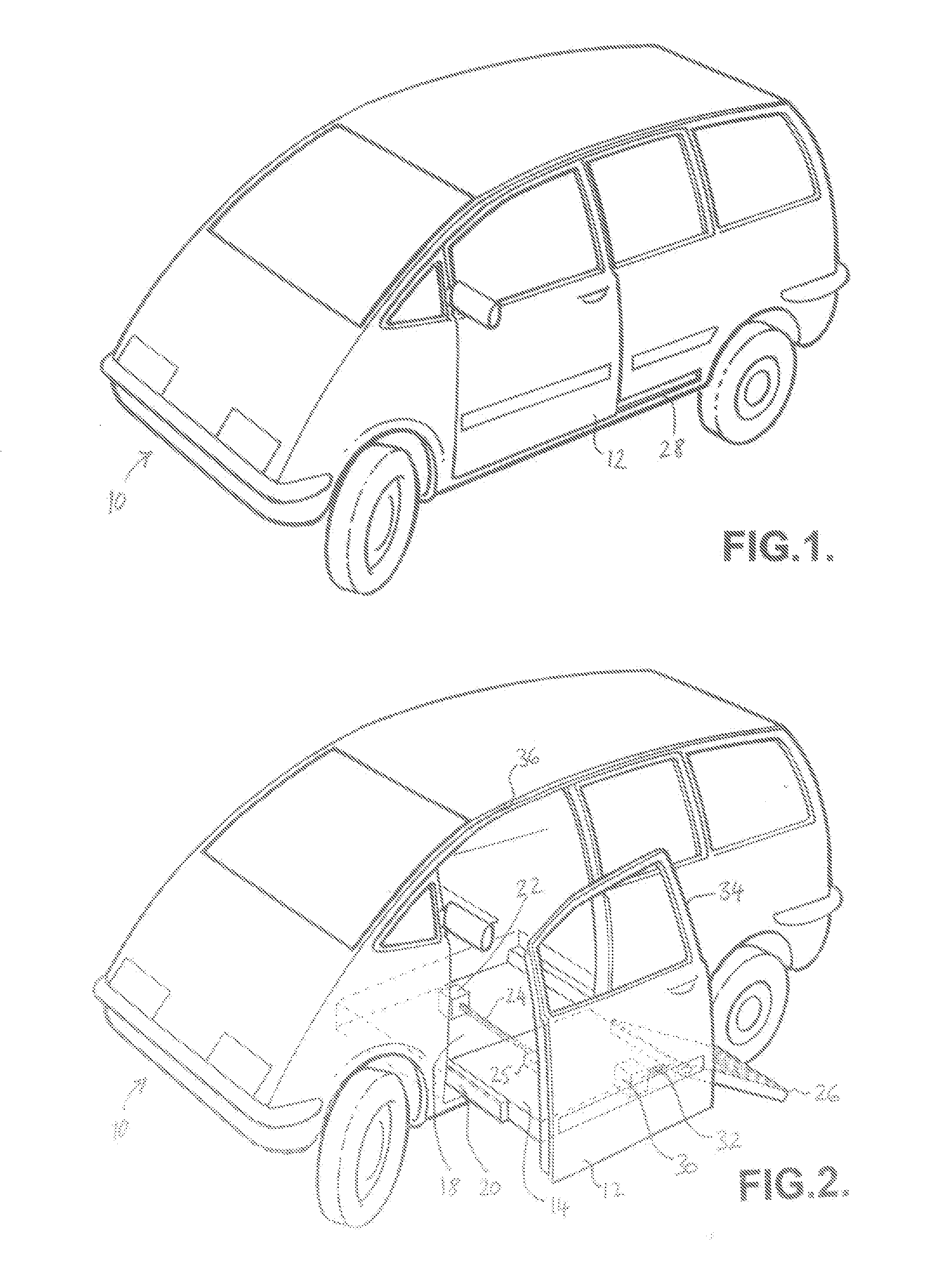
[0022] With reference to the drawings, a four-wheeled multipurpose passenger vehicle (MPV) 10 comprises a front passenger-side door 12 which is movable between a closed position illustrated in FIG. 1 and an open position illustrated in FIG. 2. As best seen in FIG. 2, the door 12 is mounted on the outer edge of a platform 14 which is movable laterally between the open and closed positions. When the platform 14 is displaced inwardly, it is received in a complementarily-shaped recess 18 formed in the floor pan of the vehicle.

[0023] The platform is mounted on runners 20, which allows the platform to slide between its open and closed positions. The platform is displaceable by means of an electric motor 22 which is arranged to rotate a screw-threadedly mounted rod 24 which in turn is threadly engaged with an internally threaded boss 25 on the undersurface of the platform 14. Rotation of the screw-threaded rod 24 in one direction displaces the platform 14 laterally outwardly and rotation ...


PUM


Abstract

The present invention relates to a vehicle comprising a vehicle body, a vehicle door releasably locatable in an access aperture of the vehicle body, a platform forming at least part of the interior floor of the vehicle and being displaceably mounted on the vehicle body adjacent to the door, and means for displacing the platform outwardly and inwardly with respect to the vehicle body through the access aperture when the door is open.

Description

CROSS-REFERENCE TO RELATED APPLICATIONS [0001] This application claims foreign priority benefits under 35 U.S.C. § 119(a)-(d) to GB 0601557.2, filed Jan. 26, 2006, which is hereby incorporated by reference in its entirety. BACKGROUND OF THE INVENTION [0002] 1. Field of the Invention The present invention relates to a vehicles and methods of modifying vehicles so as to afford better access to the side of a vehicle. The present invention is particularly useful for access to and from the vehicle from wheelchairs and for the loading of heavy and / or wheeled articles. [0003] 2. Background Art [0004] Standard cars can be modified after production in order to accommodate people with mobility problems who are wheelchair bound. This modification is necessary as the design of most cars is aimed towards fully mobile people rather than disabled drivers or passengers. [0005] Most types of cars that are modified for wheelchair users tend to be the larger cars such as multipurpose vehicles (MPV) an...

Claims


Application Information

Patent Timeline
IPC IPC(8): B60P1/00
CPCA61G3/061A61G2003/067B60J5/047A61G3/067
Inventor SAMUELS, HOWARD DANIELHEALY, BRIAN REGINALD
Owner W H ASPECT
Learn More